PIC16F877A is a 40-pin (PDIP type) microcontroller which has 5 ports: A, B, C, D and E. From the 40 pins we can use 33 pins as an I/O pins. This microcontroller has 3 timers which are:
Timer0: 8-bit timer,
Timer1: 16-bit timer,
Timer2: 8-bit timer.
This microcontroller has also 10-bit, up to 8-channel Analog-to-Digital Converter (ADC) and many other peripheral features.
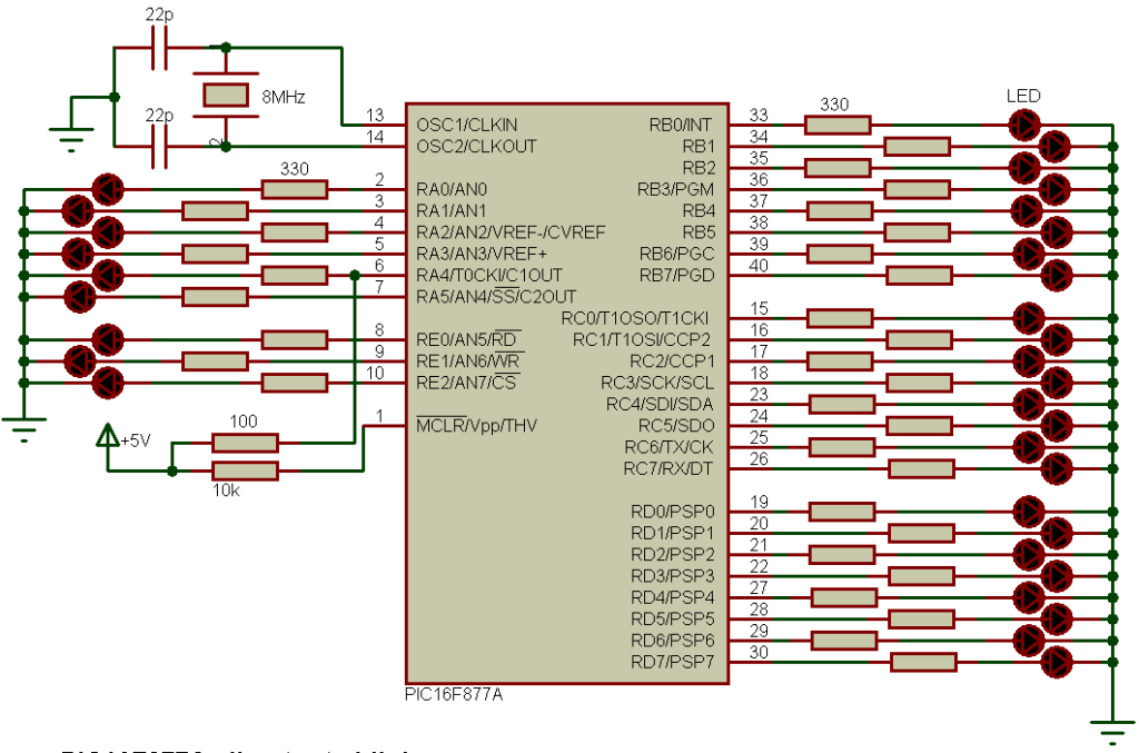
This topic shows PIC16F877A LED blink example and also shows how to make all the available outputs of the PIC16F877A microcontroller blink.
PIC16F877A LED blink example circuit:
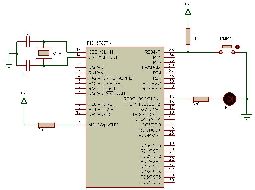
This is a small example shows how to make an LED blinking. Circuit schematic is shown below:

In this example the PIC16F877A microcontroller runs with 8MHz crystal oscillator and the LED is connected to pin RB0 through 330 ohm resistor.
Blink an LED using PIC16F877A C code:
Example C code is the one below, it was tested with CCS C compiler version 5.051.
1 2 3 4 5 6 7 8 9 10 11 12 13 14 | // PIC16F877A LED blink example // http://simple-circuit.com/ #include <16F877A.h> #use delay(crystal=8000000) void main() { while(TRUE) { output_toggle(PIN_B0); // Toggle output pin RB0 delay_ms(500); } } |
PIC16F877A make all outputs blink:
This is a second example which makes all the 33 output pins on PIC16F877A blink. Circuit schematic is below:

PIC16F877A make all outputs blink CCS PIC C code:
The C code below was also tested with CCS C compiler version 5.051.
1 2 3 4 5 6 7 8 9 10 11 12 13 14 15 16 17 18 19 20 21 22 23 24 | // PIC16F877A all outputs blink // http://simple-circuit.com/ #include <16F877A.h> #use delay(crystal=8000000) void main() { while(TRUE) { output_a(0); // All port A pins low output_b(0); // All port B pins low output_c(0); // All port C pins low output_d(0); // All port D pins low output_e(0); // All port E pins low delay_ms(500); output_a(0x3F); // All port A pins high output_b(0xFF); // All port B pins high output_c(0xFF); // All port C pins high output_d(0xFF); // All port D pins high output_e(0x07); // All port E pins high delay_ms(500); } } |
Discover more from Simple Circuit
Subscribe to get the latest posts sent to your email.


From all your examples you do not set a port direction, any reason for that?
hello, why you connect the pin number 6 to VCC ?
Because it’s an open collector output and to be high a pull-up resistor is required.