PIC16F877A buttons read
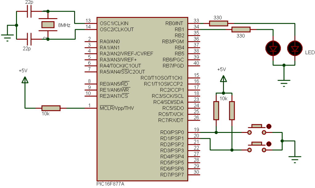
This is PIC16F877A read inputs example. LEDs are going to be controlled using push buttons as shown in the circuit schematic below.
PIC16F877A read inputs example circuit:
Example circuit schematic is shown below.
 As shown in the circuit schematic there are two push buttons and two LEDs. Each button controls one LED, the first button which is connected to RD0 toggles ON and OFF the LED connected to RB0 and the second button toggles ON and OFF the other LED.
Hardware Required:
- PIC16F877A microcontroller —> datasheet
- 1602 LCD display
- 8 MHz crystal oscillator
- 2 x 22 pF ceramic capacitor
- 10k Ohm resistor
- 10k Ohm variable resistor (or potentiometer)
- PIC microcontroller programmer (PICkit 3, PICkit 4 …)
PIC16F877A read inputs example C code:
Example C code is the one below, it was tested with CCS C compiler version 5.051.
1 2 3 4 5 6 7 8 9 10 11 12 13 14 15 16 17 18 19 20 21 22 23 | // PIC16F877A buttons read // https://simple-circuit.com/ #include <16F877A.h> #use delay(crystal=8000000) void main() { output_b(0); while(TRUE) { if(input(PIN_D0) == 0) { output_toggle(PIN_B0); delay_ms(500); } if(input(PIN_D1) == 0) { output_toggle(PIN_B1); delay_ms(500); } } } |
Discover more from Simple Circuit
Subscribe to get the latest posts sent to your email.


