PIC16F887 LCD Example (Hello world!)

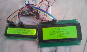
This post shows a simple example for interfacing PIC16F887 microcontroller with 16×2 and 20×4 LCDs using CCS C compiler. CCS C has a driver which allows us to control LCDs that have HD44780 or compliant controller.
Required Components:
- PIC16F887 Microcontroller
- 1602 (16×2) or 2004 (20×4) or any LCD compatible with HD44780 controller
- 10K Potentiometer
- 0.1µF Ceramic capacitor (optional)
- +5V Power source
- Breadboard
- Jumper wires
Interfacing PIC16F887 with LCD display circuit:
Circuit diagram of the example is shown below.
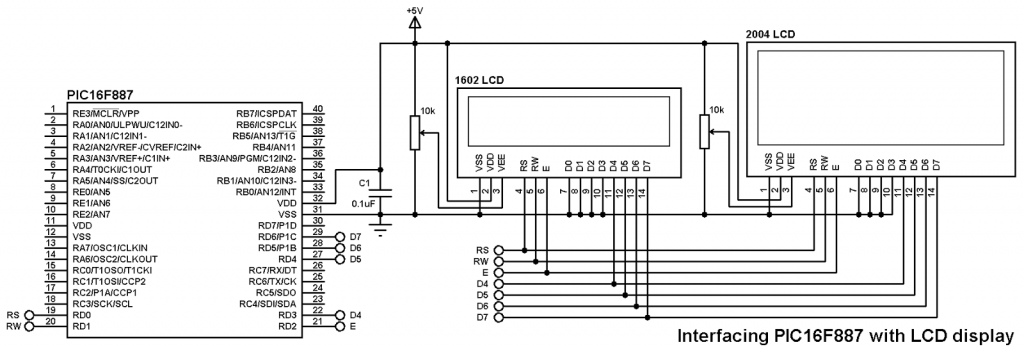
Note that the internal oscillator of the microcontroller is used and MCLR (pin 1) pin is configured as an input pin.
Interfacing PIC16F887 with LCD display CCS C code:
1 2 3 4 5 6 7 8 9 10 11 12 13 14 15 16 17 18 19 20 21 22 23 24 25 26 27 28 29 30 31 32 33 34 35 36 37 38 39 40 41 42 43 44 45 46 47 48 49 50 51 52 53 | /* PIC16F887 interfacing with 1602 (16x2) and 2004 (20x4) LCDs example CCS C code with shift left and shift right Internal oscillator used @ 4MHz */ //LCD module connections #define LCD_RS_PIN PIN_D0 #define LCD_RW_PIN PIN_D1 #define LCD_ENABLE_PIN PIN_D2 #define LCD_DATA4 PIN_D3 #define LCD_DATA5 PIN_D4 #define LCD_DATA6 PIN_D5 #define LCD_DATA7 PIN_D6 //End LCD module connections #include <16F887.h> #fuses NOMCLR NOBROWNOUT NOLVP INTRC_IO #use delay(clock = 4MHz) #include <lcd.c> unsigned int8 i; void lcd_shift_left(){ lcd_send_byte(0,0x18); // Shift left command } void lcd_shift_right(){ lcd_send_byte(0,0x1E); // Shift right command } void main(){ setup_oscillator(OSC_4MHZ); // Set the internal oscillator to 4MHz lcd_init(); // Initialize LCD module lcd_putc('\f'); // Clear LCD lcd_gotoxy(2, 1); // Go to column 2 row 1 lcd_putc("PIC16F887"); // Display "PIC16F887" delay_ms(1000); // Wait 1 second lcd_gotoxy(1, 2); // Go to column 1 row 2 lcd_putc("LCD example"); delay_ms(1000); lcd_gotoxy(21, 1); // Go to column 1 row 3 lcd_putc("Hello world!"); delay_ms(1000); for(i = 0; i < 8; i++){ lcd_shift_right(); // Shift right delay_ms(100);} for(i = 0; i < 4; i++){ lcd_shift_left(); // Shift left delay_ms(100);} for(i = 0; i < 200; i++){ lcd_gotoxy(25, 2); // Go to column 5 row 4 printf(lcd_putc,"%3u",i); // Write i with 3 numbers max delay_ms(200); } while(TRUE); // Endless loop } |
Simulation video:
This video shows the simulation using Proteus software.
Source code, hex and simulation files can be downloaded from the following link:
Download
Discover more from Simple Circuit
Subscribe to get the latest posts sent to your email.


hi, izit can share all “Interfacing PIC16F887 with LCD display” detail and c code for me? thank you
Project circuit diagram and C code are above!
Use CCS C compiler to compile the C code.