This is a small topic shows the interfacing of the microcontroller PIC18F4550 with 7-segment display and make a 4-digit counter with push button.
Related topics:
4-Digit 7-segmant display counter using PIC16F84A and CCS PIC C compiler
4-Digit digital counter using PIC16F877A and CCS C compiler
Interfacing PIC18F4550 with 7-segment display circuit:
The digital counter circuit schematic is shown below where the internal oscillator of PIC18F4550 is used at 8MHz and MCLR pin function is disabled.
The 7-segment display is common anode type.

The PIC18F4550 microcontroller is supplied with 5V at VDD (pin #11 & 32) and VSS (pin #12 & 31) pins (not shown in circuit schematic).
The push button shown in the circuit diagram is used to increment the number printed on the 7-segment display.
Hardware Required:
- PIC18F4550 microcontroller —-> datasheet
- Common anode 4-digit seven-segment display
- 4 x 2N3906 PNP transistor
- Push button
- 10k ohm resistor
- 4 x 1k ohm resistor
- 7 x 100 ohm resistor
- Bread board & jumper wires
- 5V power source
- PIC microcontroller programmer (PICkit 3, PICkit 4…)
Interfacing PIC18F4550 with 7-segment display CCS C code:
The C code below is for CCS C compiler, it was tested with version 5.051.
1 2 3 4 5 6 7 8 9 10 11 12 13 14 15 16 17 18 19 20 21 22 23 24 25 26 27 28 29 30 31 32 33 34 35 36 37 38 39 40 41 42 43 44 45 46 47 48 49 50 51 52 53 54 55 56 57 58 59 60 61 62 63 64 | // Interfacing PIC18F4550 with 7-segment display // Common anode 7-segment display used // https://simple-circuit.com/ #include <18F4550.h> #fuses NOMCLR INTRC_IO #use delay(clock=8000000) short s; // Used to know button position unsigned int digit, digit1, digit10, digit100,digit1000; unsigned long i = 0; unsigned int seg(unsigned int num) { switch (num) { case 0 : return 0xC0; case 1 : return 0xF9; case 2 : return 0xA4; case 3 : return 0xB0; case 4 : return 0x99; case 5 : return 0x92; case 6 : return 0x82; case 7 : return 0xF8; case 8 : return 0x80; case 9 : return 0x90; } } void main(){ setup_oscillator(OSC_8MHZ); while(TRUE){ if(input(PIN_D4) == 1) s = 1; if(s == 1) { if(input(PIN_D4) == 0) { s = 0; i++; if(i > 9999) i = 0; } } digit = i % 10; digit1 = seg(digit); output_d(0x0F); // Turn off all displays output_b(digit1); // Send ones digit output_d(0x07); // Turn on display for ones delay_ms(2); digit = (i / 10) % 10; digit10 = seg(digit); output_d(0x0F); // Turn off all displays output_b(digit10); // Send tens digit output_d(0x0B); // Turn on display for tens delay_ms(2); digit = (i / 100) % 10; digit100 = seg(digit); output_d(0x0F); // Turn off all displays output_b(digit100); // Send hundreds digit output_d(0x0D); // Turn on display for hundreds delay_ms(2); digit = (i / 1000) % 10; digit1000 = seg(digit); output_d(0x0F); // Turn off all displays output_b(digit1000); // Send thousands digit output_d(0x0E); // Turn on display for thousands delay_ms(2); } } |
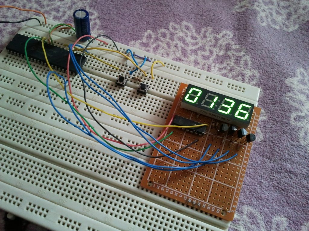
The following video shows the example in a hardware circuit.


