This topic shows how to interface DHT11 (RHT01) digital relative humidity and temperature sensor with PIC18F4550 microcontroller, and how to simulate this interfacing using Proteus.
Note that for the simulation Proteus version should be 8.1 or higher. With these versions there is no need to install Proteus DHT11 library, it is included with the software, so don’t waste your time searching for dht11 Proteus library or dhtxx.mdf or dht11 module for Proteus, just use Proteus version 8.1 or higher.
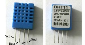
The DHT11 sensor comes in a single row 4-pin package and operates from 3.3 to 5.5V power supply. It can measure temperature from 0-50 °C with an accuracy of ±2°C and relative humidity ranging from 20-90% with an accuracy of ±5%. The sensor provides fully calibrated digital outputs for the two measurements. It has got its own proprietary 1-wire protocol, and therefore, the communication between the sensor and a microcontroller is not possible through a direct interface with any of its peripherals. The protocol must be implemented in the firmware of the MCU with precise timing required by the sensor.
 The following timing diagrams describe the data transfer protocol between a MCU and the DHT11 sensor. The MCU initiates data transmission by issuing a “Start” signal. The MCU pin must be configured as output for this purpose. The MCU first pulls the data line low for at least 18 ms and then pulls it high for next 20-40 us before it releases it. Next, the sensor responds to the MCU “Start“ signal by pulling the line low for 80 us followed by a logic high signal that also lasts for 80 us. Remember that the MCU pin must be configured to input after finishing the “Start“ signal. Once detecting the response signal from the sensor, the MCU should be ready to receive data from the sensor. The sensor then sends 40 bits (5 bytes) of data continuously in the data line. Note that while transmitting bytes, the sensor sends the most significant bit first.
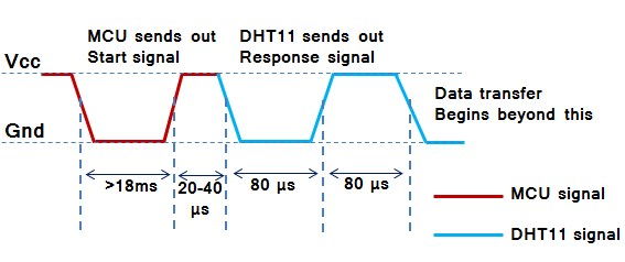 Data consists of decimal and integral parts. A complete data transmission is 40bit, and the sensor sends higher data bit first.
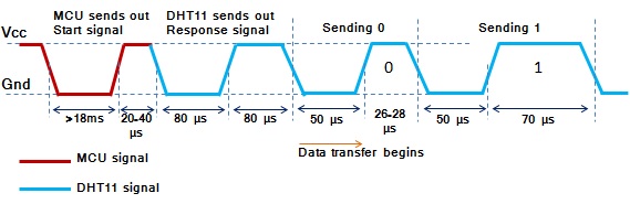
Data format: 8bit integral RH data + 8bit decimal RH data + 8bit integral T data + 8bit decimal T data + 8bit check sum. If the data transmission is right, the check-sum should be the last 8bit of “8bit integral RH data + 8bit decimal RH data + 8bit integral T data + 8bit decimal T data”.
The DHT11 is a digital sensor so it sends 1’s and 0’s, but it is very important to know how it sends the digital data. The figure below shows how the sensor sends its information.
Interfacing PIC18F4550 with DHT11 (RHT01) sensor circuit:
The following circuit schematic shows complete project circuit.
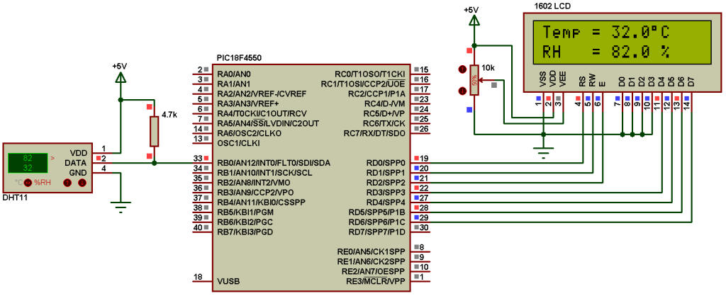
The circuit is simple, there is the microcontroller PIC18F4550, DHT11 sensor and 1602 LCD to display humidity and temperature results.
PIC18F4550 uses its internal oscillator @ 8MHz and mclr pin function is disabled.
Interfacing PIC18F4550 with DHT11(RHT01) sensor CCS C code:
The interfacing code is written with CCS PIC C compiler PCWHD version 5.051.
If you want to understand the code please read the DHT11 datasheet.
Variables Time_out and k are used to test reading time to avoid wrong data reception or microcontroller hanging.
1 2 3 4 5 6 7 8 9 10 11 12 13 14 15 16 17 18 19 20 21 22 23 24 25 26 27 28 29 30 31 32 33 34 35 36 37 38 39 40 41 42 43 44 45 46 47 48 49 50 51 52 53 54 55 56 57 58 59 60 61 62 63 64 65 66 67 68 69 70 71 72 73 74 75 76 77 78 79 80 81 82 83 84 85 86 87 88 89 90 91 92 93 94 95 96 97 98 99 100 101 102 103 104 105 106 107 108 109 110 111 112 113 114 115 116 | // Interfacing PIC18F4550 with DHT11 sensor //LCD module connections #define LCD_RS_PIN PIN_D0 #define LCD_RW_PIN PIN_D1 #define LCD_ENABLE_PIN PIN_D2 #define LCD_DATA4 PIN_D3 #define LCD_DATA5 PIN_D4 #define LCD_DATA6 PIN_D5 #define LCD_DATA7 PIN_D6 //End LCD module connections #include <18F4550.h> #fuses NOMCLR INTRC_IO #use delay(clock = 8000000) #include <lcd.c> #use fast_io(B) // Connection pin between PIC18F4550 and DHT11(RHT01) sensor #BIT Data_Pin = 0xF81.0 // Pin mapped to PORTB.0 #BIT Data_Pin_Direction = 0xF93.0 // Pin direction mapped to TRISB.0 char message1[] = "Temp = 00.0 C"; char message2[] = "RH = 00.0 %"; short Time_out; unsigned int8 T_byte1, T_byte2, RH_byte1, RH_byte2, CheckSum ; void start_signal(){ Data_Pin_Direction = 0; // Configure connection pin as output Data_Pin = 0; // Connection pin output low delay_ms(25); Data_Pin = 1; // Connection pin output high delay_us(30); Data_Pin_Direction = 1; // Configure connection pin as input } short check_response(){ delay_us(40); if(!Data_Pin){ // Read and test if connection pin is low delay_us(80); if(Data_Pin){ // Read and test if connection pin is high delay_us(50); return 1;} } } unsigned int8 Read_Data(){ unsigned int8 i, k, _data = 0; // k is used to count 1 bit reading duration if(Time_out) break; for(i = 0; i < 8; i++){ k = 0; while(!Data_Pin){ // Wait until pin goes high k++; if (k > 100) {Time_out = 1; break;} delay_us(1);} delay_us(30); if(!Data_Pin) bit_clear(_data, (7 - i)); // Clear bit (7 - i) else{ bit_set(_data, (7 - i)); // Set bit (7 - i) while(Data_Pin){ // Wait until pin goes low k++; if (k > 100) {Time_out = 1; break;} delay_us(1);} } } return _data; } void main(){ setup_oscillator(OSC_8MHZ); // Set internal oscillator to 8MHz setup_adc_ports(NO_ANALOGS); // Configure AN pins as digital lcd_init(); // Initialize LCD module lcd_putc('f'); // LCD clear while(TRUE){ delay_ms(1000); Time_out = 0; Start_signal(); if(check_response()){ // If there is response from sensor RH_byte1 = Read_Data(); // read RH byte1 RH_byte2 = Read_Data(); // read RH byte2 T_byte1 = Read_Data(); // read T byte1 T_byte2 = Read_Data(); // read T byte2 Checksum = Read_Data(); // read checksum if(Time_out){ // If reading takes long time lcd_putc('f'); // LCD clear lcd_gotoxy(5, 1); // Go to column 5 row 1 lcd_putc("Time out!"); } else{ if(CheckSum == ((RH_Byte1 + RH_Byte2 + T_Byte1 + T_Byte2) & 0xFF)){ message1[7] = T_Byte1/10 + 48; message1[8] = T_Byte1%10 + 48; message1[10] = T_Byte2/10 + 48; message2[7] = RH_Byte1/10 + 48; message2[8] = RH_Byte1%10 + 48; message2[10] = RH_Byte2/10 + 48; message1[11] = 223; // Degree symbol lcd_putc('f'); // LCD clear lcd_gotoxy(1, 1); // Go to column 1 row 1 printf(lcd_putc, message1); // Display message1 lcd_gotoxy(1, 2); // Go to column 1 row 2 printf(lcd_putc, message2); // Display message2 } else { lcd_putc('f'); // LCD clear lcd_gotoxy(1, 1); // Go to column 1 row 1 lcd_putc("Checksum Error!"); } } } else { lcd_putc('f'); // LCD clear lcd_gotoxy(3, 1); // Go to column 3 row 1 lcd_putc("No response"); lcd_gotoxy(1, 2); // Go to column 1 row 2 lcd_putc("from the sensor"); } } } |
Interfacing PIC18F4550 with DHT11 (RHT01) sensor Proteus simulation video:
The following video shows Proteus simulation of this interfacing.
DHT11 Proteus simulation file download:
DOWNLOAD
Reference:
http://embedded-lab.com/
Discover more from Simple Circuit
Subscribe to get the latest posts sent to your email.


muito bom