It is good idea to build a simple and low cost DIY remote controlled real time clock/calendar using simple components. This post show how to make a remote controlled real time clock using PIC12F1822 microcontroller, DS1307 RTC chip, NEC IR remote control and all data are displayed on 1602 LCD.
The DS1307 is an 8-pin integrated circuit uses I2C communication protocol to communicate with master device which is in our case PIC12F1822 microcontroller. This small chip can count seconds, minutes, hours, day, date, month and year with leap-year up to year 2100.
The DS1307 receives and transfers data (clock data and calendar data) as BCD format, so after receiving data we have to convert these data into decimal data, and before writing data to the DS1307 we have to convert this data from decimal to BCD format. For example we have the BCD number 33, converting this number into decimal gives 21.
PIC12F1822 microcontroller has an I2C hardware module which can work as master device. The I2C bus specifies two signal connections:
Serial Clock (SCL) (pin RA1)
Serial Data (SDA) (pin RA2)
The time and calendar are displayed on 1602 LCD display. This LCD is interfaced with the microcontroller using 74HC595 shift register as what was done in this post:
Interfacing PIC12F1822 microcontroller with LCD display
The IR remote control used in this project uses NEC communication protocol. The following post shows how this protocol works and how to decode its data with PIC12F1822:
Extended NEC Protocol Decoder Using PIC12F1822 Microcontroller
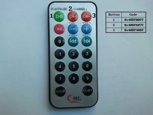
An image of the remote control used in this project with used buttons data is shown below. Only 3 buttons are used in this project and the rest of buttons have no effect on the circuit.
Components List:
- PIC12F1822 Microcontroller
- NEC Protocol IR Remote Control (Example: Car MP3)
- DS1307 RTC
- 1602 LCD
- 74HC595 Shift Register
- IR Receiver
- 47µF Capacitor
- 32.768 Crystal
- 3V Lithium Coin Cell Battery
- 10K Variable Resistor
- 3 x 10K Resistor
- +5V Power Supply
- Protoboard
- Jumper Wires
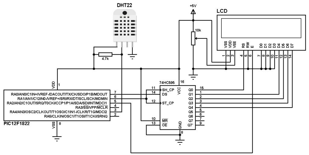
Remote controlled real time clock using PIC12F1822 and DS1307 circuit:
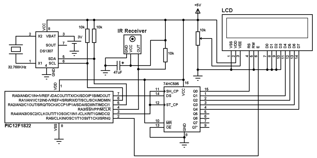
For this project internal oscillator of the microcontroller is used and MCLR pin is configured to work as a digital input pin.
The IR receiver has 3 pins: GND, VCC (+5V) and OUT. The OUT pin is connected to RA3 pin of PIC12F1822. The IR receiver is used to receive IR signals comes from the remote control and sends data to the microcontroller.
DS1307 RTC has 8 pins and only pin 7 is not used. The DS1307 RTC needs an external crystal oscillator of 32.768KHz which is connected between pins 1 & 2. A 3V coin cell Lithium battery is connected between pin 3 (VBAT) and GND. This battery is used as a backup power supply for the DS1307 whenever the main power fails, it keeps the time running without any problem. DS1307 is connected to microcontroller via two lines SCL and SDA. A pull-ups resistors must be added to the two lines because both are open drain.
The 1602 LCD display pins are connected to 74HC595 shift register except the Enable pin (E) which is connected directly to PIC12F1822. With the help of the shift register 74HC595 the LCD uses only 3 data lines: clock, data and Enable. Other types of serial-in parallel-out shift registers can be used such as 74HC164 and CD4094 (74HC4094).
Remote controlled real time clock using PIC12F1822 and DS1307 C code:
PIC12F1822 internal oscillator is used in this project at 8MHz and by enabling PLL we get a frequency of 32MHz (8 x 4).
Timer1 is configured to increment by 1 every 1us. It is used to measure IR signals spaces and pulses.
RA3 Pin interrupt is used to interrupt when the IR receiver receives an IR signal. So when the IR receiver receives a signal the output of the IR receives goes from high to low which causes the microcontroller to interrupt and starts decoding the received IR signal. Enabling RA3 interrupt is done using the following two lines:
enable_interrupts(GLOBAL);
enable_interrupts(INT_RA3_H2L);
Complete CCS C code is below, it was tested with version 5.051.
1 2 3 4 5 6 7 8 9 10 11 12 13 14 15 16 17 18 19 20 21 22 23 24 25 26 27 28 29 30 31 32 33 34 35 36 37 38 39 40 41 42 43 44 45 46 47 48 49 50 51 52 53 54 55 56 57 58 59 60 61 62 63 64 65 66 67 68 69 70 71 72 73 74 75 76 77 78 79 80 81 82 83 84 85 86 87 88 89 90 91 92 93 94 95 96 97 98 99 100 101 102 103 104 105 106 107 108 109 110 111 112 113 114 115 116 117 118 119 120 121 122 123 124 125 126 127 128 129 130 131 132 133 134 135 136 137 138 139 140 141 142 143 144 145 146 147 148 149 150 151 152 153 154 155 156 157 158 159 160 161 162 163 164 165 166 167 168 169 170 171 172 173 174 175 176 177 178 179 180 181 182 183 184 185 186 187 188 189 190 191 192 193 194 195 196 197 198 199 200 201 202 203 204 205 206 207 208 209 210 211 212 213 214 215 216 | // Real time colck/calendar with remote control using PIC12F1822 and DS1307 RTC CCS C code // 3-Wire LCD driver must be added //LCD module connections #define LCD_DATA_PIN PIN_A0 #define LCD_CLOCK_PIN PIN_A4 #define LCD_EN_PIN PIN_A5 //End LCD module connections #include <12F1822.h> #fuses NOMCLR INTRC_IO PLL_SW #use delay(clock=32000000) #include <3WireLCD.c> #use fast_io(A) #define IR_Sensor PIN_A3 #use I2C(master, I2C1, FAST = 100000) char time[] = "TIME: : : "; char calendar[] = "DATE: / /20 "; unsigned int8 second, second10, minute, minute10, hour, hour10, date, date10, month, month10, year, year10, day, i, j; unsigned int32 ir_code; unsigned int32 nec_remote_read(){ unsigned int8 k; unsigned int16 count = 0; unsigned int32 code; // Check 9ms pulse (remote control sends logic high) SET_TIMER1(0); while(!input(IR_Sensor) && (count < 9500)) count = GET_TIMER1(); if((count > 9499) || (count < 8500)) return 0; // Check 4.5ms space (remote control sends logic low) SET_TIMER1(0); count = 0; while((input(IR_Sensor)) && (count < 5000)) count = GET_TIMER1(); if((count > 4999) || (count < 4000)) return 0; // Read message (32 bits) for(k = 0; k < 32; k++){ SET_TIMER1(0); count = 0; while(!input(IR_Sensor) && (count < 650)) count = GET_TIMER1(); if((count > 649) || (count < 500)) return 0; count = 0; SET_TIMER1(0); while((input(IR_Sensor)) && (count < 1800)) count = GET_TIMER1(); if( (count > 1799) || (count < 400)) return 0; if( count > 1000) // If space width > 1ms bit_set(code, (31 - k)); // Write 1 to bit (31 - k) else // If space width < 1ms bit_clear(code, (31 - k)); // Write 0 to bit (31 - k) } return code; } #INT_RA // RB port interrupt on change void ra_isr(void){ ir_code = nec_remote_read(); clear_interrupt(INT_RA); } void ds1307_display(){ second10 = (second & 0x70) >> 4; second = second & 0x0F; minute10 = (minute & 0x70) >> 4; minute = minute & 0x0F; hour10 = (hour & 0x30) >> 4; hour = hour & 0x0F; date10 = (date & 0x30) >> 4; date = date & 0x0F; month10 = (month & 0x10) >> 4; month = month & 0x0F; year10 = (year & 0xF0) >> 4; year = year & 0x0F; time[12] = second + 48; time[11] = second10 + 48; time[9] = minute + 48; time[8] = minute10 + 48; time[6] = hour + 48; time[5] = hour10 + 48; calendar[14] = year + 48; calendar[13] = year10 + 48; calendar[9] = month + 48; calendar[8] = month10 + 48; calendar[6] = date + 48; calendar[5] = date10 + 48; lcd_goto(1, 1); // Go to column 1 row 1 printf(lcd_out, time); // Display time lcd_goto(1, 2); // Go to column 1 row 2 printf(lcd_out, calendar); // Display calendar } void ds1307_write(unsigned int8 address, data_){ i2c_start(); // Start I2C i2c_write(0xD0); // DS1307 address i2c_write(address); // Send register address i2c_write(data_); // Write data to the selected register i2c_stop(); // Stop I2C } void ds1307_read(){ i2c_start(); // Start I2C protocol i2c_write(0xD0); // DS1307 address i2c_write(0); // Send register address i2c_start(); // Restart I2C i2c_write(0xD1); // Initialize data read second =i2c_read(1); // Read seconds from register 0 minute =i2c_read(1); // Read minuts from register 1 hour = i2c_read(1); // Read hour from register 2 day = i2c_read(1); // Read day from register 3 date = i2c_read(1); // Read date from register 4 month = i2c_read(1); // Read month from register 5 year = i2c_read(0); // Read year from register 6 i2c_stop(); // Stop I2C protocol } int8 edit(int8 parameter, int8 xx, int8 yy){ ir_code = 0; while(TRUE){ if(ir_code == 0x40BF40BF){ ir_code = 0; parameter++; if(i == 1 && parameter > 23) parameter = 0; if(i == 2 && parameter > 59) parameter = 0; if(i == 3 && parameter > 31) parameter = 1; if(i == 4 && parameter > 12) parameter = 1; if(i == 5 && parameter > 99) parameter = 0; } if(ir_code == 0x40BF807F){ ir_code = 0; if(i == 1 && parameter < 1) parameter = 24; if(i == 2 && parameter < 1) parameter = 60; if(i == 3 && parameter < 2) parameter = 32; if(i == 4 && parameter < 2) parameter = 13; if(i == 5 && parameter < 1) parameter = 100; parameter--; } lcd_goto(xx, yy); printf(lcd_out,"%02u", parameter); j = 0; while((ir_code != 0x40BF00FF) && (ir_code != 0x40BF40BF) && (ir_code != 0x40BF807F) && (j < 5)){ j++; delay_ms(50);} lcd_goto(xx, yy); lcd_out(" "); j = 0; while((ir_code != 0x40BF00FF) && (ir_code != 0x40BF40BF) && (ir_code != 0x40BF807F) && (j < 5)){ j++; delay_ms(50);} if(ir_code == 0x40BF00FF){ lcd_goto(xx, yy); printf(lcd_out,"%02u", parameter); return parameter;} } } void main() { setup_oscillator(OSC_8MHZ | OSC_PLL_ON); // Set internal oscillator to 32MHz (8MHz and PLL) setup_adc_ports(NO_ANALOGS); // Configure AN pins as digital output_a(0); set_tris_a(0x0E); // Configure RA1, RA2 & RA3 as inputs lcd_initialize(); // Initialize LCD module lcd_cmd(LCD_CLEAR); // LCD Clear SETUP_TIMER_1(T1_INTERNAL | T1_DIV_BY_8); // Configure Timer 1 to increment every 1 us enable_interrupts(GLOBAL); // Enable global interrupts clear_interrupt(INT_RA); // Clear RA IOC flag bit enable_interrupts(INT_RA3_H2L); // Enable RA3 interrupt (High to low) while(TRUE){ if(ir_code == 0x40BF00FF){ // Convert BCD to decimal minute = minute + minute10 * 10; hour = hour + hour10 * 10; date = date + date10 * 10; month = month + month10 * 10; year = year + year10 * 10; // End conversion i = 1; hour = edit(hour, 6, 1); i = 2; minute = edit(minute, 9, 1); i=3; date = edit(date, 6, 2); i=4; month = edit(month, 9, 2); i=5; year = edit(year, 14, 2); ir_code = 0; // Convert decimal to BCD minute = ((minute/10) << 4) + (minute % 10); hour = ((hour/10) << 4) + (hour % 10); date = ((date/10) << 4) + (date % 10); month = ((month/10) << 4) + (month % 10); year = ((year/10) << 4) + (year % 10); // End conversion ds1307_write(1, minute); ds1307_write(2, hour); ds1307_write(4, date); ds1307_write(5, month); ds1307_write(6, year); ds1307_write(0, 0); } ds1307_read(); // Read data from DS1307 RTCC ds1307_display(); // Display time and calendar delay_ms(50); } } |
Real Time Clock/Calendar with Remote Control Video:
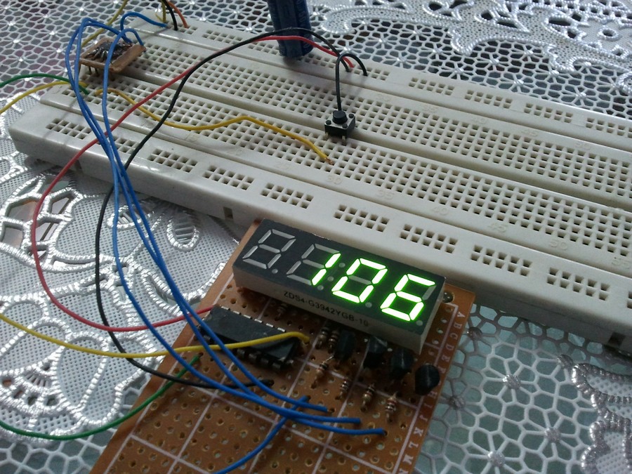
Project hardware circuit.
Discover more from Simple Circuit
Subscribe to get the latest posts sent to your email.