There are different ways to build an Arduino based real time clock, one of the ways is using a real time clock chip (like: DS1302, DS1307, DS3231 …) and another way is by using a GPS module. The GPS based clock receives time from satellites and automatically sets its time. This topic shows how to build an Arduino GPS clock with NEO-6M GPS module where time and date are displayed on 16×2 LCD screen.
Related Projects:
Last time I made a simple interfacing of Arduino with NEO-6M GPS module in order to get position, time, date and speed, project page link is below:
Interfacing Arduino with NEO-6M GPS module
Arduino GPS clock with local time using NEO-6M module
and the links below shows how to build a real time clock using Arduino and RTC chips:
Arduino real time clock with DS1307
Arduino and DS3231 real time clock
Hardware Required:
To build this project the following components are needed:
- Arduino (or compatible) board
- NEO-6M GPS module
- 16×2 LCD screen
- 10k ohm variable resistor (or potentiometer)
- 330 ohm resistor
- Breadboard
- Jumper wires

Arduino GPS real time clock with NEO-6M module circuit:
Project circuit diagram is shown below.
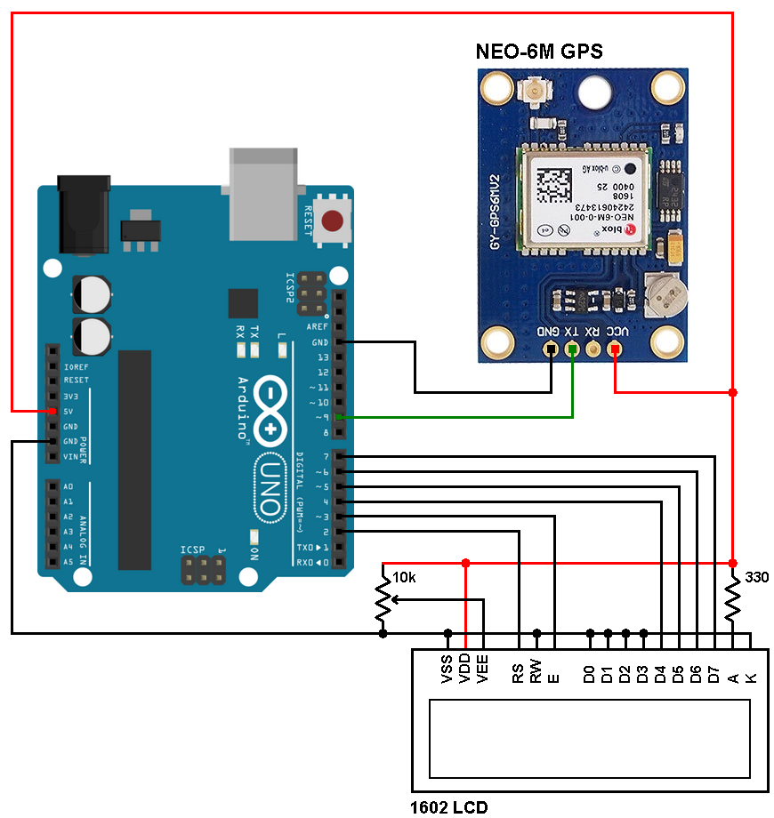
NEO-6M GPS module has 4 pins where:
NEO-6M GPS board GND pin goes to Arduino GND
TX pin goes to Arduino digital pin 9
RX pin is not connected
VCC pin goes to Arduino 5V pin (can be connected to 3.3V pin)
The 1602 LCD screen is used to display the real time clock time and date where:
RS —> Arduino digital pin 2
E —> Arduino digital pin 3
D4 —> Arduino digital pin 4
D5 —> Arduino digital pin 5
D6 —> Arduino digital pin 6
D7 —> Arduino digital pin 7
VSS, RW, D0, D1, D2, D3 and K are connected to Arduino GND (ground)
VEE to the variable resistor (or potentiometer) output
VDD to Arduino 5V and A to Arduino 5V through 330 ohm resistor
VEE pin is used to control the contrast of the LCD. A (anode) and K (cathode) are the back light LED pins.
Arduino GPS clock code:
The Arduino code below uses TinyGPS++ library, it can be downloaded from the link below. After downloading the library, unzip the folder and add it to Arduino libraries folder (for example: C:\Program Files\Arduino\libraries). You should rename the folder “TinyGPSPlus”.
TinyGPS++ Library —> direct link
Full Arduino code is below.
1 2 3 4 5 6 7 8 9 10 11 12 13 14 15 16 17 18 19 20 21 22 23 24 25 26 27 28 29 30 31 32 33 34 35 36 37 38 39 40 41 42 43 44 45 46 47 48 49 50 51 52 53 54 55 56 57 58 59 60 61 62 63 64 65 66 67 68 69 70 | // Arduino GPS real time clock with NEO-6M GPS module // https://simple-circuit.com/ #include <TinyGPS++.h> // Include TinyGPS++ library #include <SoftwareSerial.h> // Include software serial library #include <LiquidCrystal.h> // Include LCD library TinyGPSPlus gps; #define S_RX 9 // Define software serial RX pin #define S_TX 8 // Define software serial TX pin SoftwareSerial SoftSerial(S_RX, S_TX); // Configure SoftSerial library // LCD module connections (RS, E, D4, D5, D6, D7) LiquidCrystal lcd(2, 3, 4, 5, 6, 7); byte last_second; char Time[] = "TIME:00:00:00"; char Date[] = "DATE:00/00/2000"; void setup(void) { SoftSerial.begin(9600); // set up the LCD's number of columns and rows lcd.begin(16, 2); lcd.setCursor(0, 0); lcd.print(Time); // Display time lcd.setCursor(0, 1); lcd.print(Date); // Display calendar } void loop() { while (SoftSerial.available() > 0) { if (gps.encode(SoftSerial.read())) { if (gps.time.isValid()) { Time[5] = gps.time.hour() / 10 + 48; Time[6] = gps.time.hour() % 10 + 48; Time[8] = gps.time.minute() / 10 + 48; Time[9] = gps.time.minute() % 10 + 48; Time[11] = gps.time.second() / 10 + 48; Time[12] = gps.time.second() % 10 + 48; } if (gps.date.isValid()) { Date[5] = gps.date.day() / 10 + 48; Date[6] = gps.date.day() % 10 + 48; Date[8] = gps.date.month() / 10 + 48; Date[9] = gps.date.month() % 10 + 48; Date[13] =(gps.date.year() / 10) % 10 + 48; Date[14] = gps.date.year() % 10 + 48; } if(last_second != gps.time.second()) { last_second = gps.time.second(); lcd.setCursor(0, 0); lcd.print(Time); // Display time lcd.setCursor(0, 1); lcd.print(Date); // Display calendar } } } } |
The following video shows how a hardware circuit should work (UTC time):
Discover more from Simple Circuit
Subscribe to get the latest posts sent to your email.


Daniel, only just read your post. Hope you got your hours problem sorted. I live in New Zealand, and we are 13 hours ahead of GMT. I just adjusted the +48’s at the end of the “hours” lines to add the extra hours (one line corrects the 10’s, and the other corrects the 1’s of hours). In the example above, it has already been adjusted upwards by 2 hours from +48 to +50 by: Time[1] = gps.time.hour() % 10 + 50; So you would change this to +47. I hope this helps.
Sorry, I was looking at Ivos example for a 8×2 display when I said it was already set 2 hours ahead. The original sketch has all set to +48, so you would need to reduce the +48 by 3 to +45. Cheers.
Same basic code, but for 8×2 display. It shows hh:mm:ss dd/mm’yy
// Arduino GPS real time clock with NEO-6M GPS module
#include // Include TinyGPS++ library
#include // Include software serial library
#include // Include LCD library
TinyGPSPlus gps;
#define S_RX 9 // Define software serial RX pin
#define S_TX 8 // Define software serial TX pin
SoftwareSerial SoftSerial(S_RX, S_TX); // Configure SoftSerial library
// LCD module connections (RS, E, D4, D5, D6, D7)
LiquidCrystal lcd(2, 3, 4, 5, 6, 7);
byte last_second;
char Time[] = “00:00:00”;
char Date[] = “00/00’00”;
void setup(void) {
SoftSerial.begin(9600);
// set up the LCD’s number of columns and rows
lcd.begin(8, 2);
lcd.setCursor(0, 0);
lcd.print(Time); // Display time
lcd.setCursor(0, 1);
lcd.print(Date); // Display calendar
}
void loop() {
while (SoftSerial.available() > 0) {
if (gps.encode(SoftSerial.read())) {
if (gps.time.isValid()) {
Time[0] = gps.time.hour() / 10 + 48;
Time[1] = gps.time.hour() % 10 + 50;
Time[3] = gps.time.minute() / 10 + 48;
Time[4] = gps.time.minute() % 10 + 48;
Time[6] = gps.time.second() / 10 + 48;
Time[7] = gps.time.second() % 10 + 48;
}
if (gps.date.isValid()) {
Date[0] = gps.date.day() / 10 + 48;
Date[1] = gps.date.day() % 10 + 48;
Date[3] = gps.date.month() / 10 + 48;
Date[4] = gps.date.month() % 10 + 48;
Date[6] =(gps.date.year() / 10) % 10 + 48;
Date[7] = gps.date.year() % 10 + 48;
}
if(last_second != gps.time.second()) {
last_second = gps.time.second();
lcd.setCursor(0, 0);
lcd.print(Time); // Display time
lcd.setCursor(0, 1);
lcd.print(Date); // Display calendar
}
}
}
}
I did everytging the same as in the video but when i run the code it doesnt show anything on the LCD-Display.
GPS time show on P10 Display, anybody can help me
I plan to build a drone this summer and am learning to use this GPS module, thanks for the sketch and diagrams. It worked first time, now I have moved the date to the first line before the time (shorter year and no seconds to make room) and now my bottom line is blank. I plan to put the lat/long coords there. Thanks again.
Only mistakes .VSS, RW, D0, D1, D2, D3 and K errors themselves are connected to the Arduino GND (ground). D0, D1, D2, D3 They cannot be connected to GND ground! Because the LCD display may be damaged!
I have tried to load the sketch but on uploading it errors on line 39 “expected identifier before “if”
any ideas on this
Thank you very much for this awesme tutorial !
Unfortunately my “extension” failed completely. Any help is appreciated.
// update number of satellites
if (gps.satellites.isValid())
{
NumberSat = gps.satellites.value() ;
}
Thank You. Works perfectly for me with a’ GoouuuTech’ clone GPS receiver. This even gives me a 1PPS output, which is very useful for synchronising other clocks.
Does the above code also apply to Ublox M8N GPS module …?
The LCD does not seem to display any thing other than back light.
I ddnt put a 10k Pot
Hi,
can we use other GPS receiver as G-STAR IV BR355S4
I need a little help
I’m working on a project for a local church.
It is necessary to ring the bells every day at 7 am and 7 pm.
The bells are connected with relay.
What I need to add to code to turn on the relay at 7 am and 7 pm.
OK it worked; thank you very much
Very good but, my watch is showing 3 hours early, for example, 14:00 is showing 17:00; Brazil is -3 hours. Thank you
This project may help you:
https://simple-circuit.com/arduino-gps-clock-local-time-neo-6m/
Yes, I’m doing this in the 16×2 display sketch; I changed the Time Zone as follows:
from: #define time_offset 3600
to: #define time_offset -7200 (Brazil -3) but nothing is changing on the display.
What about 3rd and 4th rows?
I want to adapt the code “Arduino GPS clock with local time using NEO-6M module” in the sketch “Arduino GPS real time clock with NEO-6M module” for the Display 16×2 because I need to change the Timezone in Display 16×2.
Daniel, only just read your post. Hope you got your hours problem sorted. I live in New Zealand, and we are 13 hours ahead of GMT. I just adjusted the +48’s at the end of the “hours” lines to add the extra hours (one line corrects the 10’s, and the other corrects the 1’s of hours). In the example above, it has already been adjusted upwards by 2 hours from +48 to +50 by: Time[1] = gps.time.hour() % 10 + 50; So you would change this to +47. I hope this helps.
Thank you for your clear tutorial and code. It works well.
Your wiring diagram shows connection from the GPS to the Arduino on Digital pin 9 but your text description says “TX pin goes to Arduino digital pin 4 “. The code is written for pin 9 so I guess it’s just a typo.
Yes you’re right, now it’s corrected.
Thank you.
this module we need to connect to the Internet?
No need for an internet connection.
The Arduino is getting the time from the GPS unit.
It is reading the data from the GPS unit (line 37) through a serial connection (connected to pins 8 and 9) then extracting the time and date from that GPS data (lines 39 thru 55).
no