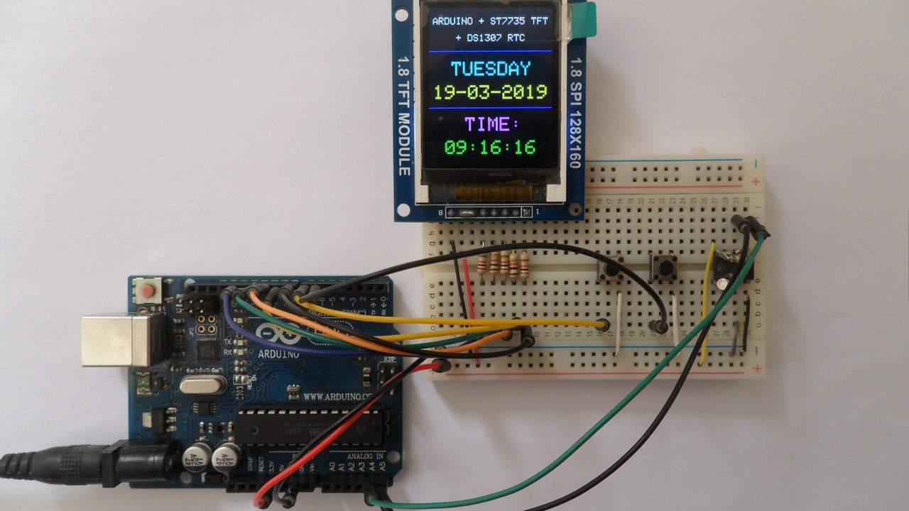
This post shows how to build a real time clock & calendar with color TFT display using Arduino UNO board and DS1307 RTC chip.
In this project time and date are displayed on ST7735 SPI TFT display (128 x 160 pixel resolution) and they could be set with two push buttons connected to the Arduino board.
To see how to interface Arduino with ST7735 TFT display, visit the following post:
Arduino ST7735 1.8″ TFT display example
Hardware Required:
- Arduino board
- ST7735S (ST7735R) TFT screen
- DS1307 RTC —-> datasheet
- 32.768 kHz crystal oscillator
- 2 x 10k ohm resistor
- 5 x 1k ohm resistor
- 2 x push button
- 3V coin cell battery
- Breadboard
- Jumper wires
Arduino clock with ST7735 display and DS1307 circuit:
The following image shows project circuit schematic diagram.
The ST7735S shown in the circuit diagram has 8 pins: (from right to left): RST (reset), CE (chip enable), DC (or D/C: data/command), DIN (data in), CLK (clock), VCC (5V or 3.3V), BL (back light) and Gnd (ground).

Normally the ST7735 display works with 3.3V only, but many boards of this display have a built-in 3.3V regulator (AMS1117 3V3) like the one shown in the circuit diagram. This regulator supplies the display controller with 3.3V from 5V source.
All Arduino UNO board output pins are 5V, connecting a 5V pin to the ST7735 display board may damage its controller circuit. To avoid that, I connected each control line of the display to the Arduino board through 1k ohm resistor.
So, the ST7735 display is connected to the Arduino board as follows (each one through 1k resistor):
RST pin is connected to Arduino digital pin 8
CS pin is connected to Arduino digital pin 9
D/C pin is connected to Arduino digital pin 10
DIN pin is connected to Arduino digital pin 11
CLK pin is connected to Arduino digital pin 13
The DS1307 RTC SDA (serial data) and SCL (serial clock) pins are respectively connected to Arduino A4 and A5 pins (ATmega328P hardware I2C module pins).
Arduino clock with ST7735 display and DS1307 code:
The following Arduino code requires 3 libraries from Adafruit Industries:
Adafruit ST7735 display library
Adafruit graphics library —-> direct link
Adafruit RTC library —-> direct link
After the download, go to Arduino IDE —> Sketch —> Include Library —> Add .ZIP Library … and browse for the .zip file (previously downloaded).
The same thing for the other library files.
The 3 libraries are included in the main code as follows:
1 2 3 | #include <Adafruit_GFX.h> // include Adafruit graphics library #include <Adafruit_ST7735.h> // include Adafruit ST7735 TFT library #include <RTClib.h> // include Adafruit RTC library |
The ST7735 TFT display is connected to Arduino hardware SPI module pins (clock and data), the other pins which are: RST (reset), CS (chip select) and DC (data/command) are defined as shown below:
1 2 3 | #define TFT_RST 8 // TFT RST pin is connected to arduino pin 8 #define TFT_CS 9 // TFT CS pin is connected to arduino pin 9 #define TFT_DC 10 // TFT DC pin is connected to arduino pin 10 |
And the two push buttons are defined in the code as:
1 2 3 | // button definitions #define button1 7 // button B1 is connected to Arduino pin 7 #define button2 6 // button B2 is connected to Arduino pin 6 |
Functions used in the code:
bool debounce (): this function is for button B1 debounce, returns 1 if button is debounced.
void RTC_display(): displays day of the week, date and time on the display.
byte edit(byte parameter): this function is for setting the real time clock, returns the edited parameter.
Rest of code is described through comments.
Full Arduino code:
1 2 3 4 5 6 7 8 9 10 11 12 13 14 15 16 17 18 19 20 21 22 23 24 25 26 27 28 29 30 31 32 33 34 35 36 37 38 39 40 41 42 43 44 45 46 47 48 49 50 51 52 53 54 55 56 57 58 59 60 61 62 63 64 65 66 67 68 69 70 71 72 73 74 75 76 77 78 79 80 81 82 83 84 85 86 87 88 89 90 91 92 93 94 95 96 97 98 99 100 101 102 103 104 105 106 107 108 109 110 111 112 113 114 115 116 117 118 119 120 121 122 123 124 125 126 127 128 129 130 131 132 133 134 135 136 137 138 139 140 141 142 143 144 145 146 147 148 149 150 151 152 153 154 155 156 157 158 159 160 161 162 163 164 165 166 167 168 169 170 171 172 173 | /* * Arduino real time clock using DS1307 and ST7735 TFT (128x160 pixel) * This is a free software with NO WARRANTY. * http://simple-circuit.com/ */ #include <Adafruit_GFX.h> // include Adafruit graphics library #include <Adafruit_ST7735.h> // include Adafruit ST7735 TFT library #include "RTClib.h" // include Adafruit RTC library #define TFT_RST 8 // TFT RST pin is connected to arduino pin 8 #define TFT_CS 9 // TFT CS pin is connected to arduino pin 9 #define TFT_DC 10 // TFT DC pin is connected to arduino pin 10 // initialize ST7735 TFT library Adafruit_ST7735 tft = Adafruit_ST7735(TFT_CS, TFT_DC, TFT_RST); // initialize RTC library RTC_DS1307 rtc; DateTime now; // buttons definition #define button1 7 // button B1 is connected to Arduino pin 7 #define button2 6 // button B2 is connected to Arduino pin 6 void setup(void) { pinMode(button1, INPUT_PULLUP); pinMode(button2, INPUT_PULLUP); rtc.begin(); // initialize RTC chip tft.initR(INITR_BLACKTAB); // initialize a ST7735S chip, black tab tft.fillScreen(ST7735_BLACK); // fill screen with black color tft.drawFastHLine(0, 44, tft.width(), ST7735_BLUE); // draw horizontal blue line at position (0, 44) tft.drawFastHLine(0, 102, tft.width(), ST7735_BLUE); // draw horizontal blue line at position (0, 102) tft.setTextColor(ST7735_WHITE, ST7735_BLACK); // set text color to white and black background tft.setTextSize(1); // text size = 1 tft.setCursor(4, 10); // move cursor to position (4, 10) pixel tft.print("ARDUINO + ST7735 TFT"); tft.setCursor(28, 27); // move cursor to position (28, 27) pixel tft.print("+ DS1307 RTC"); tft.setTextSize(2); // text size = 2 tft.setTextColor(ST7735_MAGENTA, ST7735_BLACK); // set text color to magneta and black background tft.setCursor(37, 112); // move cursor to position (37, 112) pixel tft.print("TIME:"); } // a small function for button1 (B1) debounce bool debounce () { byte count = 0; for(byte i = 0; i < 5; i++) { if ( !digitalRead(button1) ) count++; delay(10); } if(count > 2) return 1; else return 0; } void RTC_display() { char _buffer[11]; char dow_matrix[7][10] = {"SUNDAY", "MONDAY", "TUESDAY", "WEDNESDAY", "THURSDAY", "FRIDAY", "SATURDAY"}; byte x_pos[7] = {29, 29, 23, 11, 17, 29, 17}; static byte previous_dow = 8; // print day of the week if( previous_dow != now.dayOfTheWeek() ) { previous_dow = now.dayOfTheWeek(); tft.fillRect(11, 55, 108, 14, ST7735_BLACK); // draw rectangle (erase day from the display) tft.setCursor(x_pos[previous_dow], 55); tft.setTextColor(ST7735_CYAN, ST7735_BLACK); // set text color to cyan and black background tft.print( dow_matrix[now.dayOfTheWeek()] ); } // print date sprintf( _buffer, "%02u-%02u-%04u", now.day(), now.month(), now.year() ); tft.setCursor(4, 79); tft.setTextColor(ST7735_YELLOW, ST7735_BLACK); // set text color to yellow and black background tft.print(_buffer); // print time sprintf( _buffer, "%02u:%02u:%02u", now.hour(), now.minute(), now.second() ); tft.setCursor(16, 136); tft.setTextColor(ST7735_GREEN, ST7735_BLACK); // set text color to green and black background tft.print(_buffer); } byte edit(byte parameter) { static byte i = 0, y_pos, x_pos[5] = {4, 40, 100, 16, 52}; char text[3]; sprintf(text,"%02u", parameter); if(i < 3) { tft.setTextColor(ST7735_YELLOW, ST7735_BLACK); // set text color to green and black background y_pos = 79; } else { tft.setTextColor(ST7735_GREEN, ST7735_BLACK); // set text color to yellow and black background y_pos = 136; } while( debounce() ); // call debounce function (wait for B1 to be released) while(true) { while( !digitalRead(button2) ) { // while B2 is pressed parameter++; if(i == 0 && parameter > 31) // if day > 31 ==> day = 1 parameter = 1; if(i == 1 && parameter > 12) // If month > 12 ==> month = 1 parameter = 1; if(i == 2 && parameter > 99) // If year > 99 ==> year = 0 parameter = 0; if(i == 3 && parameter > 23) // if hours > 23 ==> hours = 0 parameter = 0; if(i == 4 && parameter > 59) // if minutes > 59 ==> minutes = 0 parameter = 0; sprintf(text,"%02u", parameter); tft.setCursor(x_pos[i], y_pos); tft.print(text); delay(200); // wait 200ms } tft.fillRect(x_pos[i], y_pos, 22, 14, ST7735_BLACK); unsigned long previous_m = millis(); while( (millis() - previous_m < 250) && digitalRead(button1) && digitalRead(button2)) ; tft.setCursor(x_pos[i], y_pos); tft.print(text); previous_m = millis(); while( (millis() - previous_m < 250) && digitalRead(button1) && digitalRead(button2)) ; if(!digitalRead(button1)) { // if button B1 is pressed i = (i + 1) % 5; // increment 'i' for the next parameter return parameter; // return parameter value and exit } } } void loop() { if( !digitalRead(button1) ) // if B1 is pressed if( debounce() ) // call debounce function (make sure B1 is pressed) { while( debounce() ); // call debounce function (wait for B1 to be released) byte day = edit( now.day() ); // edit date byte month = edit( now.month() ); // edit month byte year = edit( now.year() - 2000 ); // edit year byte hour = edit( now.hour() ); // edit hours byte minute = edit( now.minute() ); // edit minutes // write time & date data to the RTC chip rtc.adjust(DateTime(2000 + year, month, day, hour, minute, 0)); while(debounce()); // call debounce function (wait for button B1 to be released) } now = rtc.now(); // read current time and date from the RTC chip RTC_display(); // diaplay time & calendar delay(100); // wait 100ms } // end of code. |
The following video shows my protoboard circuit test:
Discover more from Simple Circuit
Subscribe to get the latest posts sent to your email.


