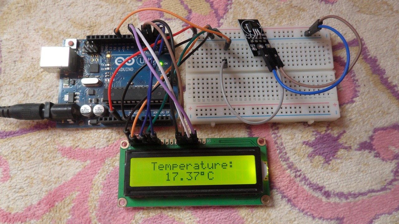
This post shows how to build a simple thermometer using Arduino UNO board and DS18B20 digital temperature sensor where the temperature value is displayed on 16×2 LCD screen and sent serially to Arduino IDE serial monitor.
The DS18B20 sensor is a 3-pin electronic component (like a simple transistor) from Maxim (formerly Dallas) which uses 1-wire protocol to communicate with master device (microprocessor, microcontroller ….). Each DS18B20 device has a unique 64-bit serial code, which allows multiple DS18B20s to function on the same 1-Wire bus and controlled with one master device.
The DS18B20 sensor provides 9-bit to 12-bit Celsius temperature measurement resolution (programmable resolution).
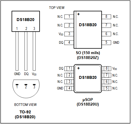
The DS18B20 sensor is available in 8-Pin SO (150 mils), 8-Pin μSOP, and 3-Pin TO-92 Packages. DS18B20 pin configurations is shown below:
Hardware Required:
- Arduino board
- DS18B20 temperature sensor — datasheet
- 16×2 LCD screen
- 4.7k ohm resistor
- Breadboard
- Jumper wires
Interfacing Arduino with DS18B20 temperature sensor circuit:
Example circuit schematic diagram is shown below.
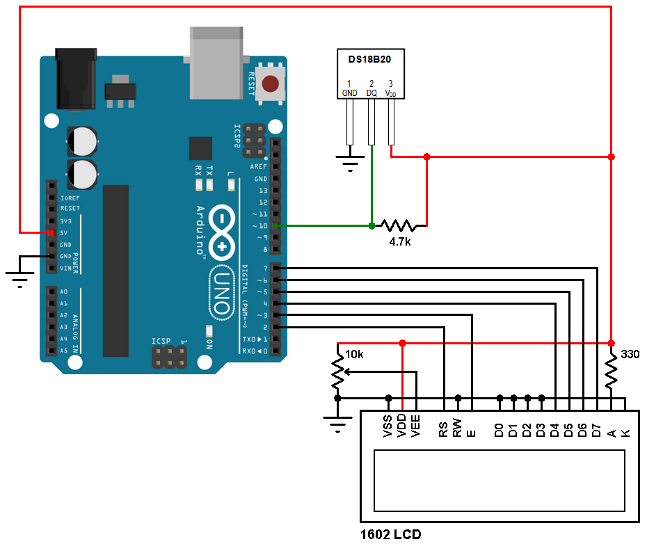
All grounded terminals are connected together.
The DS18B20 sensor has 3 pins: VCC (+5V), data and GND. The data pin is connected to Arduino pin 10.
The LCD screen is used to display the temperature value read by the DS18B20 sensor.
Arduino with DS18B20 sensor code:
Example Arduino code is below, it doesn’t use any library for the DS18B20 sensor, the only library used is for the LCD display.
Functions used in the code:
bool ds18b20_start(): used to know if the DS18B20 sensor is correctly connected to the circuit, returns 1 if OK and 0 if error.
ds18b20_write_bit(bool value): writes (sends) 1 bit to the DS18B20 sensor, the bit is ‘value’ which may be 1 or 0.
ds18b20_write_byte(byte value): writes 1 byte (8 bits) to the DS18B20 sensor, this function is based on the previous function. This function writes LSB first.
bool ds18b20_read_bit(void): reads 1 bit from the DS18B20 sensor, returns the read value (1 or 0).
byte ds18b20_read_byte(void): reads 1 byte from the DS18B20 sensor, this function is based on the previous function. This function reads LSB first.
bool ds18b20_read(int *raw_temp_value): reads the temperature raw data which is 16-bit long (two 8-bit registers), the data is stored in the variable raw_temp_value, returns 1 if OK and 0 if error.
The value of the temperature in degree Celsius is equal to the raw value divided by 16 (in case of 12-bit resolution). The default resolution of the DS18B20 is 12 bits.
1 2 3 4 5 6 7 8 9 10 11 12 13 14 15 16 17 18 19 20 21 22 23 24 25 26 27 28 29 30 31 32 33 34 35 36 37 38 39 40 41 42 43 44 45 46 47 48 49 50 51 52 53 54 55 56 57 58 59 60 61 62 63 64 65 66 67 68 69 70 71 72 73 74 75 76 77 78 79 80 81 82 83 84 85 86 87 88 89 90 91 92 93 94 95 96 97 98 99 100 101 102 103 104 105 | // Interfacing Arduino with DS18B20 temperature sensor #include <LiquidCrystal.h> // include LCD library code #define DS18B20_PIN 10 // LCD module connections (RS, E, D4, D5, D6, D7) LiquidCrystal lcd(2, 3, 4, 5, 6, 7); int raw_temp; float temp; char txt[] = " C "; void setup(void) { // start serial port Serial.begin(9600); // set up the LCD's number of columns and rows lcd.begin(16, 2); txt[0] = 223; // Put degree symbol (°) lcd.setCursor(2, 0); lcd.print("Temperature:"); } void loop(void) { if(ds18b20_read(&raw_temp)) { Serial.print("Temperature = "); temp = (float)raw_temp / 16; // Convert temperature raw value into degree Celsius (temp in °C = raw/16) Serial.print(temp); // Print temperature value in degree Celsius Serial.println("°C"); // Print '°C' // Display temperature on LCD lcd.setCursor(4, 1); lcd.print(temp); lcd.print(txt); } else { Serial.println("Communication Error!"); lcd.setCursor(4, 1); lcd.print(" Error! "); } delay(1000); } bool ds18b20_start(){ bool ret = 0; digitalWrite(DS18B20_PIN, LOW); // Send reset pulse to the DS18B20 sensor pinMode(DS18B20_PIN, OUTPUT); delayMicroseconds(500); // Wait 500 us pinMode(DS18B20_PIN, INPUT); delayMicroseconds(100); //wait to read the DS18B20 sensor response if (!digitalRead(DS18B20_PIN)) { ret = 1; // DS18B20 sensor is present delayMicroseconds(400); // Wait 400 us } return(ret); } void ds18b20_write_bit(bool value){ digitalWrite(DS18B20_PIN, LOW); pinMode(DS18B20_PIN, OUTPUT); delayMicroseconds(2); digitalWrite(DS18B20_PIN, value); delayMicroseconds(80); pinMode(DS18B20_PIN, INPUT); delayMicroseconds(2); } void ds18b20_write_byte(byte value){ byte i; for(i = 0; i < 8; i++) ds18b20_write_bit(bitRead(value, i)); } bool ds18b20_read_bit(void) { bool value; digitalWrite(DS18B20_PIN, LOW); pinMode(DS18B20_PIN, OUTPUT); delayMicroseconds(2); pinMode(DS18B20_PIN, INPUT); delayMicroseconds(5); value = digitalRead(DS18B20_PIN); delayMicroseconds(100); return value; } byte ds18b20_read_byte(void) { byte i, value; for(i = 0; i <8; i++) bitWrite(value, i, ds18b20_read_bit()); return value; } bool ds18b20_read(int *raw_temp_value) { if (!ds18b20_start()) // Send start pulse return(0); // Return 0 if error ds18b20_write_byte(0xCC); // Send skip ROM command ds18b20_write_byte(0x44); // Send start conversion command while(ds18b20_read_byte() == 0); // Wait for conversion complete if (!ds18b20_start()) // Send start pulse return(0); // Return 0 if error ds18b20_write_byte(0xCC); // Send skip ROM command ds18b20_write_byte(0xBE); // Send read command *raw_temp_value = ds18b20_read_byte(); // Read temperature LSB byte and store it on raw_temp_value LSB byte *raw_temp_value |= (unsigned int)(ds18b20_read_byte() << 8); // Read temperature MSB byte and store it on raw_temp_value MSB byte return(1); // OK --> return 1 } |
Arduino with DS18B20 video:
The video below shows a simple Proteus simulation of this project.
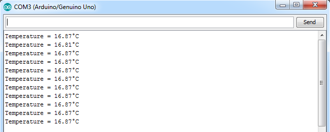
Arduino IDE serial monitor output:
Arduino + DS18B20 Proteus simulation file download:
Reference:
DS18B20 datasheet
Discover more from Simple Circuit
Subscribe to get the latest posts sent to your email.


how i convert it into farenhite
Thanks a lot for the source code!!!
First off all thank You for great tutorials you provided!
And my question: Could You explain how should I change Your Arduino code to make DS18B20+PAR sensor work properly?
DS18B20+PAR works in specific Parasite-Power mode. As I can see time intervals in Your code should be changed. But I can’t understand how.
very nice