Adding a display to an embedded system can significantly enhance its functionality by providing visual feedback and an interactive user interface. This tutorial shows how to interface Arduino development board with ST7789 color TFT display.
Abbreviations:
TFT: Thin-Film Transistor.
SPI: Serial Peripheral Interface.
IPS: In-Plane Switching.
MOSI: Master Out Slave In.
MISO: Master In Slave Out.
DIY: Do-It-Yourself
The ST7789 Color TFT Display:
The ST7789 is a display controller/driver chip for 262K-color, graphic type TFT-LCD, originally manufactured by Sitronix Technology Corp ( —ST7789 datasheet— ).
The ST7789 display is commonly used in projects involving microcontrollers like Arduino, ESP32, and Raspberry Pi. Here are some key features and aspects of the ST7789 TFT display:
- Display Controller: This display is based on a controller chip of the same name, ST7789 (or, ST7789V, ST7789VW), providing an interface between the master device and the display panel.
- Color TFT-LCD: It is specifically designed for color displays, supporting 16-bit (65,536 colors) and 18-bit (262,144 colors) color modes, providing rich color display capabilities.
- Resolution: The ST7789 displays come with different resolutions (320×240 pixel, 240×240 pixel…) supporting landscape and portrait orientations. Common resolutions are 240×240 pixels and 240×320 pixels.
- Communication Interface: It usually interfaces with microcontrollers or other devices using SPI (Serial Peripheral Interface).
- Supported Operations: The ST7789 TFT display supports standard display operations such as drawing pixels, lines, rectangles, and displaying images.
- Display Orientation: Can be rotated to multiple orientations (0, 90, 180, 270 degrees) through software commands.
- Low Power Consumption: It is designed to be power-efficient, suitable for battery-powered or low-power devices.
- Voltage Levels: The ST7789 typically works 3.3V, and the specific requirements may vary based on the module or display being used.
- Widely Used in Projects: The ST7789 is often used in DIY electronics projects, especially those involving microcontrollers like Arduino, Raspberry Pi, STM32, and others.
The following image shows a ST7789 display module provided by Adafruit Industries:

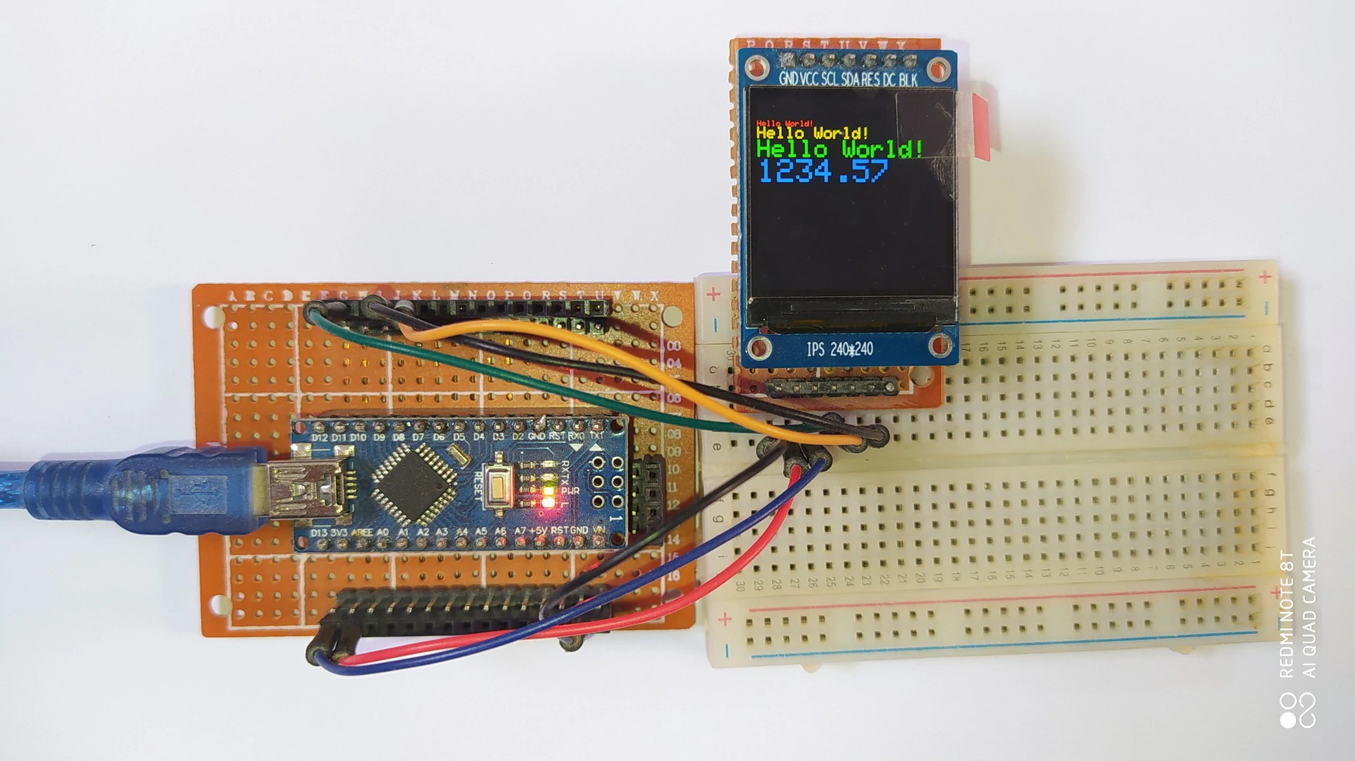
Another version of the ST7789 display module is shown below, it is the one used in this tutorial. This one has no CS (chip select) pin that internally attached to GND. The resolution of this display is 240×240 pixel.
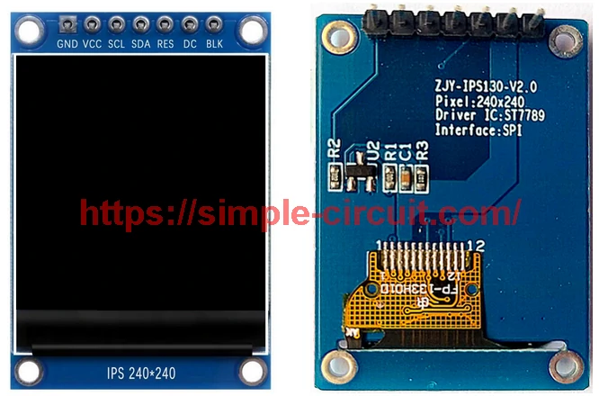
ST7789 color TFT display module pin description:
- GND: Ground connection pin.
- VCC: Power supply voltage pin.
- SCL: Serial Clock pin. Connected to the SPI clock pin of the master device.
- SDA: Serial Data Input pin. Connected to the SPI MOSI (Master Out Slave In) pin of the master device.
- RES: Reset signal pin. Connected to a digital output pin on the master device. It is often optional, and if not used, it could be connected to master device reset pin or tied to a stable low level point.
- DC (Data/Command): Data/Command control signal. Connected to a digital output pin on the master device. It determines whether the data on the bus is a command or actual pixel data.
- BLK (Backlight): Backlight control pin. Connected to a digital output or PWM (Pulse Width Modulation) pin on the master device, it could be connected to VCC for maximum and permanent backlight on the display.
If the display has a CS pin:
- CS: Chip Select pin. Connected to a digital pin on the master device. Used to enable or disable the communication with the ST7789 display.
Hardware Required:
- Arduino UNO or similar board —> Board details.
- ST7789 TFT display module.
- 4 x 3.3k ohm resistor (+1 if the display module has CS pin).
- 4 x 2.2k ohm resistor (+1 if the display module has CS pin).
- Breadboard & jumper wires.
Interfacing Arduino with ST7789 TFT Display Circuit:
Project circuit schematic diagram is shown below.
The ST7789 display module shown in project circuit diagram has 7 pins: (from left to right): GND (ground), VCC, SCL (serial clock), SDA (serial data), RES (reset), DC (or D/C: data/command) and BLK (back light).
The ST7789 display used in this project works with voltage level of 3.3V only, this includes power supply and data/control signals. Note that all Arduino UNO board output pins are 5V, connecting a 5V output pin to the ST7789 TFT display may damage its controller chip.
For the power supply, the ST7789 display is supplied with 3.3V from the Arduino board. For data & control signals, I used resistor voltage divider for each line to scale down the Arduino 5V into 3V. Each voltage divider consists of 2.2k and 3.3k resistors.
Connection between the Arduino and the ST7789 display:
The ST7789 display is connected to the Arduino board as follows:
GND is connected to pin GND of the Arduino board.
VCC and BLK pins are connected to pin 3V3 of the Arduino board.
SCL pin is connected to pin 13 of the Arduino board (through voltage divider).
SDA pin is connected to pin 11 of the Arduino board (through voltage divider).
RST pin is connected to pin 8 of the Arduino board (through voltage divider).
DC pin is connected to pin 9 of the Arduino board (through voltage divider).
If the display module has a CS pin then it should be connected to pin 10 of the Arduino board through another resistive voltage divider.
Pins 13 and 11 are hardware SPI module pins of the ATmega328P microcontroller, respectively for SCK (serial clock) and MOSI (master-out slave-in).
Interfacing Arduino with ST7789 Color TFT Display Code:
Project Arduino code is just an example of graphics test provided by Adafruit Industries, with some minor modifications.
To be able to compile project Arduino code, two libraries are required from Adafruit Industries:
The first library is a driver for the ST7789 TFT display which can be installed from Arduino IDE library manager (Sketch —> Include Library —> Manage Libraries…, in the search box write “st7789” and install the one from Adafruit).
The second library is Adafruit graphics library which can be installed also from Arduino IDE library manager.
During installation of the Adafruit ST7789 library, Arduino IDE may ask for installing some other libraries form Adafruit Industries (dependencies).
Project code was tested with the following library versions:
Adafruit GFX Library: Version 1.11.9.
Adafruit ST7735 and ST7789 Library: Version 1.10.4.
Programming Hints:
The used libraries are included in the Arduino code as shown below:
1 2 3 | #include <Adafruit_GFX.h> // Include Adafruit Core graphics library #include <Adafruit_ST7789.h> // Include Adafruit Hardware-specific library for ST7789 #include <SPI.h> // Include Arduino SPI library |
The connection between the Arduino UNO board and the ST7789 TFT display is as shown in the above circuit schematic, it is defined in the Arduino code as shown below:
1 2 3 4 | // Define ST7789 display pin connection #define TFT_CS 10 #define TFT_RST 8 // Or set to -1 and connect to Arduino RESET pin #define TFT_DC 9 |
The initialization of the ST7789 TFT display library with the connections previously defined:
1 2 | // Initialize the ST7789 display library with previously defined connections Adafruit_ST7789 tft = Adafruit_ST7789(TFT_CS, TFT_DC, TFT_RST); |
The ST7789 display must be initialized before any print operation, if the initialization failed then the display will show only black screen. The initialization function of the display is the one below:
1 2 | // Initialize the ST7789 TFT display tft.init(240, 240, SPI_MODE3); // Init ST7789 240x240 |
If the display failed to initialize properly then you have to try with another SPI Mode, replace SPI_MODE3 by one of the following:
SPI_MODE0
SPI_MODE1
SPI_MODE2
For more details about Arduino SPI communication, see the following page:
Arduino & Serial Peripheral Interface (SPI)
Rest of code is described through comments.
Full Arduino code:
1 2 3 4 5 6 7 8 9 10 11 12 13 14 15 16 17 18 19 20 21 22 23 24 25 26 27 28 29 30 31 32 33 34 35 36 37 38 39 40 41 42 43 44 45 46 47 48 49 50 51 52 53 54 55 56 57 58 59 60 61 62 63 64 65 66 67 68 69 70 71 72 73 74 75 76 77 78 79 80 81 82 83 84 85 86 87 88 89 90 91 92 93 94 95 96 97 98 99 100 101 102 103 104 105 106 107 108 109 110 111 112 113 114 115 116 117 118 119 120 121 122 123 124 125 126 127 128 129 130 131 132 133 134 135 136 137 138 139 140 141 142 143 144 145 146 147 148 149 150 151 152 153 154 155 156 157 158 159 160 161 162 163 164 165 166 167 168 169 170 171 172 173 174 175 176 177 178 179 180 181 182 183 184 185 186 187 188 189 190 191 192 193 194 195 196 197 198 199 200 201 202 203 204 205 206 207 208 209 210 211 212 213 214 215 216 217 218 219 220 221 222 223 224 225 226 227 228 229 230 231 232 233 234 235 236 237 238 239 240 241 242 243 244 245 246 247 248 249 250 251 252 253 254 255 256 257 258 259 260 261 262 263 264 265 266 267 268 269 270 271 272 273 274 275 276 277 278 279 280 281 282 283 284 285 286 287 288 289 290 291 292 293 294 295 296 297 298 299 300 301 302 303 304 305 306 307 308 309 310 311 312 313 314 315 | /************************************************************************************** * Interfacing Arduino board with ST7789 TFT display (240x240 pixel). * This is a free software with NO WARRANTY. * https://simple-circuit.com/ /**************************************************************************************/ #include <Adafruit_GFX.h> // Include Adafruit Core graphics library #include <Adafruit_ST7789.h> // Include Adafruit Hardware-specific library for ST7789 #include <SPI.h> // Include Arduino SPI library // Define ST7789 display pin connection #define TFT_CS 10 #define TFT_RST 8 // Or set to -1 and connect to Arduino RESET pin #define TFT_DC 9 // Initialize the ST7789 display library with previously defined connections Adafruit_ST7789 tft = Adafruit_ST7789(TFT_CS, TFT_DC, TFT_RST); float p = 3.1415926; void setup(void) { Serial.begin(9600); Serial.print(F("Hello! ST77xx TFT Test")); // Initialize the ST7789 TFT display tft.init(240, 240, SPI_MODE3); // Init ST7789 240x240 // if the screen is flipped, remove this command tft.setRotation(2); Serial.println(F("Initialized")); uint16_t time = millis(); tft.fillScreen(ST77XX_BLACK); time = millis() - time; Serial.println(time, DEC); delay(500); // large block of text tft.fillScreen(ST77XX_BLACK); testdrawtext("Lorem ipsum dolor sit amet, consectetur adipiscing elit. Curabitur adipiscing ante sed nibh tincidunt feugiat. Maecenas enim massa, fringilla sed malesuada et, malesuada sit amet turpis. Sed porttitor neque ut ante pretium vitae malesuada nunc bibendum. Nullam aliquet ultrices massa eu hendrerit. Ut sed nisi lorem. In vestibulum purus a tortor imperdiet posuere. ", ST77XX_WHITE); delay(1000); // tft print function! tftPrintTest(); delay(4000); // a single pixel tft.drawPixel(tft.width()/2, tft.height()/2, ST77XX_GREEN); delay(500); // line draw test testlines(ST77XX_YELLOW); delay(500); // optimized lines testfastlines(ST77XX_RED, ST77XX_BLUE); delay(500); testdrawrects(ST77XX_GREEN); delay(500); testfillrects(ST77XX_YELLOW, ST77XX_MAGENTA); delay(500); tft.fillScreen(ST77XX_BLACK); testfillcircles(10, ST77XX_BLUE); testdrawcircles(10, ST77XX_WHITE); delay(500); testroundrects(); delay(500); testtriangles(); delay(500); mediabuttons(); delay(500); Serial.println("done"); delay(1000); } void loop() { tft.invertDisplay(true); delay(500); tft.invertDisplay(false); delay(500); } void testlines(uint16_t color) { tft.fillScreen(ST77XX_BLACK); for (int16_t x=0; x < tft.width(); x+=6) { tft.drawLine(0, 0, x, tft.height()-1, color); delay(0); } for (int16_t y=0; y < tft.height(); y+=6) { tft.drawLine(0, 0, tft.width()-1, y, color); delay(0); } tft.fillScreen(ST77XX_BLACK); for (int16_t x=0; x < tft.width(); x+=6) { tft.drawLine(tft.width()-1, 0, x, tft.height()-1, color); delay(0); } for (int16_t y=0; y < tft.height(); y+=6) { tft.drawLine(tft.width()-1, 0, 0, y, color); delay(0); } tft.fillScreen(ST77XX_BLACK); for (int16_t x=0; x < tft.width(); x+=6) { tft.drawLine(0, tft.height()-1, x, 0, color); delay(0); } for (int16_t y=0; y < tft.height(); y+=6) { tft.drawLine(0, tft.height()-1, tft.width()-1, y, color); delay(0); } tft.fillScreen(ST77XX_BLACK); for (int16_t x=0; x < tft.width(); x+=6) { tft.drawLine(tft.width()-1, tft.height()-1, x, 0, color); delay(0); } for (int16_t y=0; y < tft.height(); y+=6) { tft.drawLine(tft.width()-1, tft.height()-1, 0, y, color); delay(0); } } void testdrawtext(char *text, uint16_t color) { tft.setCursor(0, 0); tft.setTextColor(color); tft.setTextWrap(true); tft.print(text); } void testfastlines(uint16_t color1, uint16_t color2) { tft.fillScreen(ST77XX_BLACK); for (int16_t y=0; y < tft.height(); y+=5) { tft.drawFastHLine(0, y, tft.width(), color1); } for (int16_t x=0; x < tft.width(); x+=5) { tft.drawFastVLine(x, 0, tft.height(), color2); } } void testdrawrects(uint16_t color) { tft.fillScreen(ST77XX_BLACK); for (int16_t x=0; x < tft.width(); x+=6) { tft.drawRect(tft.width()/2 -x/2, tft.height()/2 -x/2 , x, x, color); } } void testfillrects(uint16_t color1, uint16_t color2) { tft.fillScreen(ST77XX_BLACK); for (int16_t x=tft.width()-1; x > 6; x-=6) { tft.fillRect(tft.width()/2 -x/2, tft.height()/2 -x/2 , x, x, color1); tft.drawRect(tft.width()/2 -x/2, tft.height()/2 -x/2 , x, x, color2); } } void testfillcircles(uint8_t radius, uint16_t color) { for (int16_t x=radius; x < tft.width(); x+=radius*2) { for (int16_t y=radius; y < tft.height(); y+=radius*2) { tft.fillCircle(x, y, radius, color); } } } void testdrawcircles(uint8_t radius, uint16_t color) { for (int16_t x=0; x < tft.width()+radius; x+=radius*2) { for (int16_t y=0; y < tft.height()+radius; y+=radius*2) { tft.drawCircle(x, y, radius, color); } } } void testtriangles() { tft.fillScreen(ST77XX_BLACK); uint16_t color = 0xF800; int t; int w = tft.width()/2; int x = tft.height()-1; int y = 0; int z = tft.width(); for(t = 0 ; t <= 15; t++) { tft.drawTriangle(w, y, y, x, z, x, color); x-=4; y+=4; z-=4; color+=100; } } void testroundrects() { tft.fillScreen(ST77XX_BLACK); uint16_t color = 100; int i; int t; for(t = 0 ; t <= 4; t+=1) { int x = 0; int y = 0; int w = tft.width()-2; int h = tft.height()-2; for(i = 0 ; i <= 16; i+=1) { tft.drawRoundRect(x, y, w, h, 5, color); x+=2; y+=3; w-=4; h-=6; color+=1100; } color+=100; } } void tftPrintTest() { tft.setTextWrap(false); tft.fillScreen(ST77XX_BLACK); tft.setCursor(0, 30); tft.setTextColor(ST77XX_RED); tft.setTextSize(1); tft.println("Hello World!"); tft.setTextColor(ST77XX_YELLOW); tft.setTextSize(2); tft.println("Hello World!"); tft.setTextColor(ST77XX_GREEN); tft.setTextSize(3); tft.println("Hello World!"); tft.setTextColor(ST77XX_BLUE); tft.setTextSize(4); tft.print(1234.567); delay(1500); tft.setCursor(0, 0); tft.fillScreen(ST77XX_BLACK); tft.setTextColor(ST77XX_WHITE); tft.setTextSize(0); tft.println("Hello World!"); tft.setTextSize(1); tft.setTextColor(ST77XX_GREEN); tft.print(p, 6); tft.println(" Want pi?"); tft.println(" "); tft.print(8675309, HEX); // print 8,675,309 out in HEX! tft.println(" Print HEX!"); tft.println(" "); tft.setTextColor(ST77XX_WHITE); tft.println("Sketch has been"); tft.println("running for: "); tft.setTextColor(ST77XX_MAGENTA); tft.print(millis() / 1000); tft.setTextColor(ST77XX_WHITE); tft.print(" seconds."); } void mediabuttons() { // play tft.fillScreen(ST77XX_BLACK); tft.fillRoundRect(25, 10, 78, 60, 8, ST77XX_WHITE); tft.fillTriangle(42, 20, 42, 60, 90, 40, ST77XX_RED); delay(500); // pause tft.fillRoundRect(25, 90, 78, 60, 8, ST77XX_WHITE); tft.fillRoundRect(39, 98, 20, 45, 5, ST77XX_GREEN); tft.fillRoundRect(69, 98, 20, 45, 5, ST77XX_GREEN); delay(500); // play color tft.fillTriangle(42, 20, 42, 60, 90, 40, ST77XX_BLUE); delay(50); // pause color tft.fillRoundRect(39, 98, 20, 45, 5, ST77XX_RED); tft.fillRoundRect(69, 98, 20, 45, 5, ST77XX_RED); // play color tft.fillTriangle(42, 20, 42, 60, 90, 40, ST77XX_GREEN); } /************************************************************************** This is a library for several Adafruit displays based on ST77* drivers. Works with the Adafruit 1.8" TFT Breakout w/SD card ----> http://www.adafruit.com/products/358 The 1.8" TFT shield ----> https://www.adafruit.com/product/802 The 1.44" TFT breakout ----> https://www.adafruit.com/product/2088 The 1.14" TFT breakout ----> https://www.adafruit.com/product/4383 The 1.3" TFT breakout ----> https://www.adafruit.com/product/4313 The 1.54" TFT breakout ----> https://www.adafruit.com/product/3787 The 1.69" TFT breakout ----> https://www.adafruit.com/product/5206 The 2.0" TFT breakout ----> https://www.adafruit.com/product/4311 as well as Adafruit raw 1.8" TFT display ----> http://www.adafruit.com/products/618 Check out the links above for our tutorials and wiring diagrams. These displays use SPI to communicate, 4 or 5 pins are required to interface (RST is optional). Adafruit invests time and resources providing this open source code, please support Adafruit and open-source hardware by purchasing products from Adafruit! Written by Limor Fried/Ladyada for Adafruit Industries. MIT license, all text above must be included in any redistribution **************************************************************************/ |
Interfacing Arduino with ST7789 Color TFT Display Video:
The video below shows my DIY test hardware circuit of a Arduino UNO with ST7789 TFT display:
Discover more from Simple Circuit
Subscribe to get the latest posts sent to your email.


The omitted CS pin was presumably a design decision to keep the size compact. There is a tricky solderable solution that loses the BLK pin function. Alternatively it is possible to make an adapter that gives the screen a CS function – and can also do level shifting for a 5v Arduino down to a required 3v3 device..
A 74HC245 octal non-inverting transceiver with VCC 3v3 has very good input clamp capability. An input series resistor of 1k (or 4k7) limits the current from an Arduino 5v output to a few hundred microamps.
The transceiver DIR is locked to one direction – passing through the SCL, SDA, DC, RST signals. The tristate Output Enable is used as the spoofed active LOW SPI CS for the device. The CS signal with compatible timing delay could also be passed through if only level shifting was required for use for more generic screens..NB. All unused 74HC inputs must be grounded.
Output 10k0 pull-ups keep the screen’s inputs stable when CS is not selected. The SPI_MODE2 is needed to ensure the Arduino idles SPI SCL at HIGH. It appears that all other connected SPI devices may need to have the same mode – even though it is presumed to be configurable for each device.
The screen seems to do its own Reset at power-up – unless it was a quirk of my breadboard. It is assumed that driver RST is issued with idle SCL. It has proved possible to connect a Schottky diode between RST (cathode) and CS inputs. Thus the RST LOW drives CS LOW to allow the RST signal through the buffer. The screen is not otherwise affected as SCL is HIGH.
The 3v3 is supplied locally by a simple regulator from the 5v line from the Arduino.
Blanking in the current implementation is achieved by a 5v SPST NO reed relay locally shorting BLK to ground. That keeps the Backlight path resistance much lower than it would be over my nearly 2m of 8 way cable.
The 74HC245 was chosen from a set of possible 74HC tristate buffers (eg 241, 243) as it offered a compact symmetrical layout on 2.54mm stripboard.