This Arduino tutorial shows how to interface the Uno board with ILI9341 TFT display.
The ILI9341 TFT module contains a display controller with the same name: ILI9341. It’s a color display that uses SPI interface protocol and requires 4 or 5 control pins, it’s low cost and easy to use. The resolution of this TFT display is 240 x 320 which means it has 76800 pixels. This module works with 3.3V only and it doesn’t support 5V (not 5V tolerant).
TFT: Thin-Film Transistor.
SPI: Serial Peripheral Interface.
About the ILI9341 TFT Display Module:
The ILI9341 is a popular TFT display controller, used in small to medium-sized displays for embedded systems and DIY projects. It is widely utilized in various electronic projects due to its rich set of features and simplicity. Here are some key features and specifications of the ILI9341 TFT display module:
- Resolution: 240×320 pixels.
- Screen Size: Typically around 2.2 to 3.2 inches diagonally.
- Color Depth: 16-bit (65K colors) to 18-bit (262K colors).
- Interface: SPI (Serial Peripheral Interface.
- Backlight: LED backlight.
- Touchscreen Capability: Most ILI9341 displays come with a resistive touchscreen with an integrated touch screen controller (XPT2046).
- SD Card slot: Some ILI9341 display modules come with SD card slot, this removes the need for an external SD card module.
The image shows the ILI9341 TFT module with integrated component details:
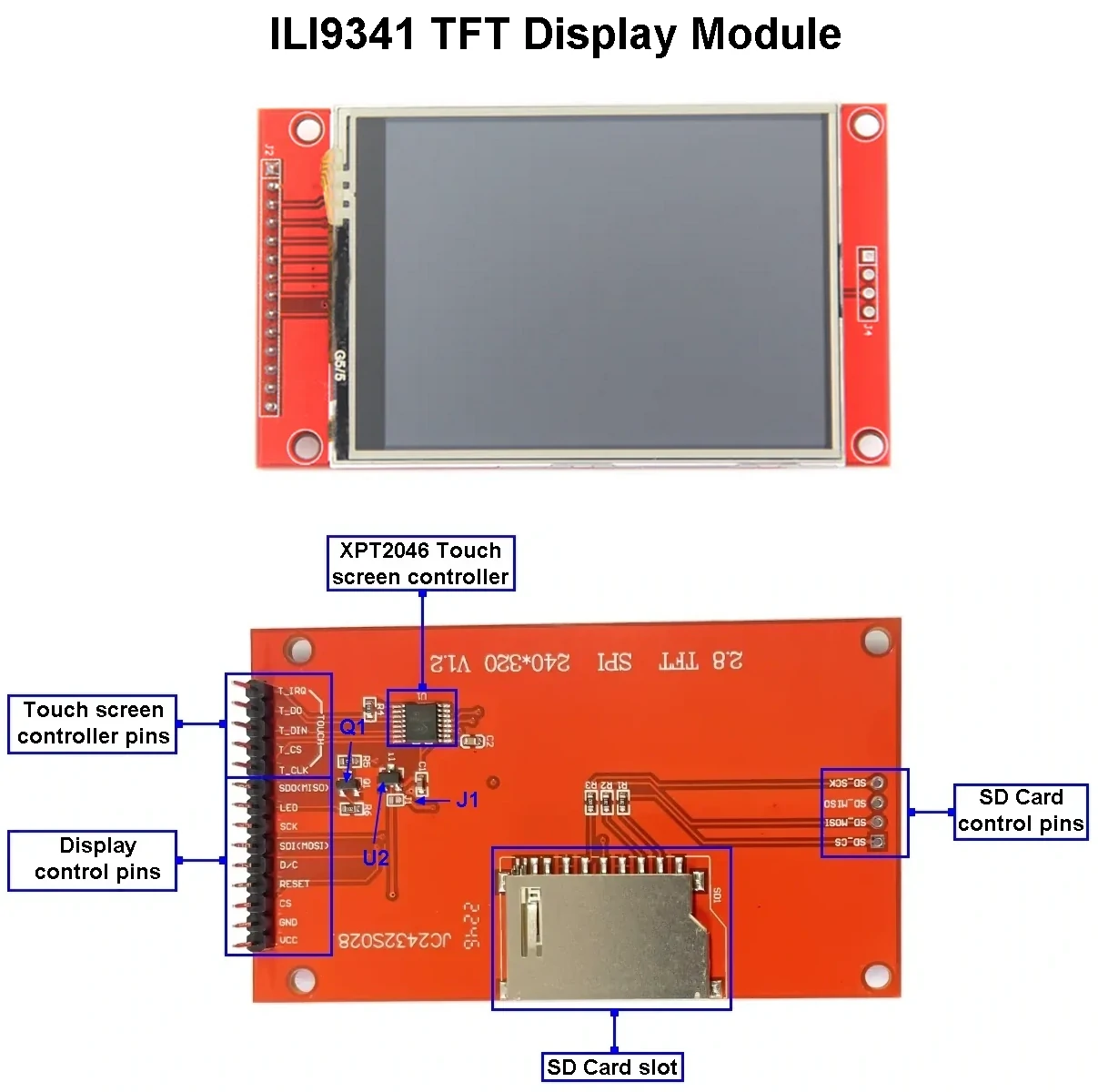
The ILI9341 display module shown above has a built-in 5V to 3.3V LDO regulator labeled as U2, the part number of this regulator is: XC6206P332MR (662K). The display module can operate with 3.3V or 5V depending on the state of jumper J1, closing the jumper will bypass the LDO regulator and configure the display to work with 3.3V only.
The ILI9341 display module consists of XPT2046 resistive touch screen controller ( —datasheet— ). This controller adds the touch screen functionality to the display.
The small transistor Q1 is used for display backlight control.
ILI9341 TFT Display Pinout:
The pinout for an ILI9341 TFT display can vary depending on the used module. For the display module shown above, pinout configuration are listed below according to their functionality.
Display Pins:
- VCC: Power supply pin, 3.3V or 5V.
- GND: Ground.
- CS: Chip Select pin, active low.
- RESET: Display reset pin, active low.
- D/C: Data/Command pin, select data or command input mode to the display, low for data mode and high for command mode.
- SDI (MOSI): Master-Out Slave-In pin, SPI data input to the display.
- SCK: SPI clock input to the display.
- LED: Backlight LED pin
- SDO/MISO: Master-In Slave-Out pin, SPI data output from the display.
Touch Screen Controller Pins (SPI Interface):
- T_CLK: Clock input.
- T_CS: Chip Select pin.
- T_DIN: Data input.
- T_DO: Data output.
- T_IRQ: Interrupt output.
SD Card Slot Pins:
- SD_CS: Chip Select.
- SD MOSI: SPI data input to the SD card.
- SD_MISO: SPI data output from the SD card.
- SD_SCK: SPI clock input to the SD card.
Hardware Required:
Required components are listed below.
- Arduino UNO (or similar) board —> Board details
- ILI9341 TFT display module
- 5 x 3.3k ohm resistor
- 5 x 2.2k ohm resistor
- Breadboard
- Jumper wires

Interfacing Arduino with ILI9341 TFT display circuit:
Hardware circuit diagram of the example is shown below.
![]()
The ILI9341 TFT display board which is shown in the circuit diagram above has 14 pins, the first 9 pins are for the display and the other 5 pins are for the touch module.
So, the display side pins which numbered from 1 to 9 are (from left to right): VCC (5V), GND (ground), CS (chip select), RST (reset), DC (or D/C: data/command), MOSI (or SDI), SCK (clock), BL (back light LED) and MISO (or SDO).
MOSI: master-out slave-in.
SDI: serial data in.
MISO: master-in slave-out.
SDO: serial data out.
As mentioned above, the ILI9341 TFT display controller works with 3.3V only (power supply and control lines). The display module is supplied with 5V that comes from the Arduino board. This module has a built-in 3.3V regulator which supplies the display controller with 3.3V from the 5V source.
All Arduino UNO board output pins are 5V, connecting a 5V pin to the ILI9341 TFT display may damage its controller.
To connect the Arduino to the display module, I used voltage divider for each line which means there are 5 voltage dividers. Each voltage divider consists of 2.2k and 3.3k resistors, this drops the 5V into 3V which is sufficient.
So, the ILI9341 TFT display is connected to the Arduino board as follows (each one through voltage divider):
CS pin is connected to Arduino digital pin 8,
RST pin is connected to Arduino digital pin 9,
D/C pin is connected to Arduino digital pin 10,
MOSI pin is connected to Arduino digital pin 11,
SCK pin is connected to Arduino digital pin 13.
Other pins are connected as follows:
VCC pin is connected to Arduino 5V pin,
GND pin is connected to Arduino GND pin,
BL (LED) pin is connected to Arduino 5V pin,
MISO pin is not connected.
Interfacing Arduino with ILI9341 TFT display code:
The following Arduino code requires two libraries from Adafruit Industries:
The first library is a driver for the ILI9341 TFT display which can be installed from Arduino IDE library manager (Sketch —> Include Library —> Manage Libraries …, in the search box write “ili9341” and choose the one from Adafruit).
The second library is Adafruit graphics library which can be installed also from Arduino IDE library manager.
The previous two libraries can also be installed manually:
Download both libraries from the following two links:
Adafruit ILI9341 TFT library —-> direct link
Adafruit graphics library —-> direct link
Go to Arduino IDE —> Sketch —> Include Library —> Add .ZIP Library … and browse for the .zip file (previously downloaded).
The same thing for the second file.
This example was tested with the following library versions:
Adafruit ILI9341 Library: 1.6.0.
Adafruit GFX Library: 1.11.9.
The previous 2 libraries are included in the main code as shown below:
1 2 | #include <Adafruit_GFX.h> // include Adafruit graphics library #include <Adafruit_ILI9341.h> // include Adafruit ILI9341 TFT library |
The ILI9341 TFT display is connected to Arduino hardware SPI module pins (clock and data), the other pins which are: CS (chip select), RST (reset) and DC (data/command) are defined as shown below:
1 2 3 | #define TFT_CS 8 // TFT CS pin is connected to arduino pin 8 #define TFT_RST 9 // TFT RST pin is connected to arduino pin 9 #define TFT_DC 10 // TFT DC pin is connected to arduino pin 10 |
Full Arduino code:
The following Arduino code is from Adafruit ILI9341 library (graphicstest.ino) with some modifications in order to work with the above circuit diagram.
1 2 3 4 5 6 7 8 9 10 11 12 13 14 15 16 17 18 19 20 21 22 23 24 25 26 27 28 29 30 31 32 33 34 35 36 37 38 39 40 41 42 43 44 45 46 47 48 49 50 51 52 53 54 55 56 57 58 59 60 61 62 63 64 65 66 67 68 69 70 71 72 73 74 75 76 77 78 79 80 81 82 83 84 85 86 87 88 89 90 91 92 93 94 95 96 97 98 99 100 101 102 103 104 105 106 107 108 109 110 111 112 113 114 115 116 117 118 119 120 121 122 123 124 125 126 127 128 129 130 131 132 133 134 135 136 137 138 139 140 141 142 143 144 145 146 147 148 149 150 151 152 153 154 155 156 157 158 159 160 161 162 163 164 165 166 167 168 169 170 171 172 173 174 175 176 177 178 179 180 181 182 183 184 185 186 187 188 189 190 191 192 193 194 195 196 197 198 199 200 201 202 203 204 205 206 207 208 209 210 211 212 213 214 215 216 217 218 219 220 221 222 223 224 225 226 227 228 229 230 231 232 233 234 235 236 237 238 239 240 241 242 243 244 245 246 247 248 249 250 251 252 253 254 255 256 257 258 259 260 261 262 263 264 265 266 267 268 269 270 271 272 273 274 275 276 277 278 279 280 281 282 283 284 285 286 287 288 289 290 291 292 293 294 295 296 297 298 299 300 301 302 303 304 305 306 307 308 309 310 311 312 313 314 315 316 317 318 319 320 321 322 323 324 325 326 327 328 329 330 331 332 333 334 335 336 337 338 339 340 341 342 343 344 345 346 347 348 349 350 | /*************************************************** This is our GFX example for the Adafruit ILI9341 Breakout and Shield ----> http://www.adafruit.com/products/1651 Check out the links above for our tutorials and wiring diagrams These displays use SPI to communicate, 4 or 5 pins are required to interface (RST is optional) Adafruit invests time and resources providing this open source code, please support Adafruit and open-source hardware by purchasing products from Adafruit! Written by Limor Fried/Ladyada for Adafruit Industries. MIT license, all text above must be included in any redistribution **************************************************** This is a free software with NO WARRANTY. https://simple-circuit.com/ ****************************************************/ #include <Adafruit_GFX.h> // include Adafruit graphics library #include <Adafruit_ILI9341.h> // include Adafruit ILI9341 TFT library #define TFT_CS 8 // TFT CS pin is connected to arduino pin 8 #define TFT_RST 9 // TFT RST pin is connected to arduino pin 9 #define TFT_DC 10 // TFT DC pin is connected to arduino pin 10 // initialize ILI9341 TFT library Adafruit_ILI9341 tft = Adafruit_ILI9341(TFT_CS, TFT_DC, TFT_RST); void setup() { Serial.begin(9600); Serial.println("ILI9341 Test!"); tft.begin(); // read diagnostics (optional but can help debug problems) uint8_t x = tft.readcommand8(ILI9341_RDMODE); Serial.print("Display Power Mode: 0x"); Serial.println(x, HEX); x = tft.readcommand8(ILI9341_RDMADCTL); Serial.print("MADCTL Mode: 0x"); Serial.println(x, HEX); x = tft.readcommand8(ILI9341_RDPIXFMT); Serial.print("Pixel Format: 0x"); Serial.println(x, HEX); x = tft.readcommand8(ILI9341_RDIMGFMT); Serial.print("Image Format: 0x"); Serial.println(x, HEX); x = tft.readcommand8(ILI9341_RDSELFDIAG); Serial.print("Self Diagnostic: 0x"); Serial.println(x, HEX); Serial.println(F("Benchmark Time (microseconds)")); Serial.print(F("Screen fill ")); Serial.println(testFillScreen()); delay(500); Serial.print(F("Text ")); Serial.println(testText()); delay(3000); Serial.print(F("Lines ")); Serial.println(testLines(ILI9341_CYAN)); delay(500); Serial.print(F("Horiz/Vert Lines ")); Serial.println(testFastLines(ILI9341_RED, ILI9341_BLUE)); delay(500); Serial.print(F("Rectangles (outline) ")); Serial.println(testRects(ILI9341_GREEN)); delay(500); Serial.print(F("Rectangles (filled) ")); Serial.println(testFilledRects(ILI9341_YELLOW, ILI9341_MAGENTA)); delay(500); Serial.print(F("Circles (filled) ")); Serial.println(testFilledCircles(10, ILI9341_MAGENTA)); Serial.print(F("Circles (outline) ")); Serial.println(testCircles(10, ILI9341_WHITE)); delay(500); Serial.print(F("Triangles (outline) ")); Serial.println(testTriangles()); delay(500); Serial.print(F("Triangles (filled) ")); Serial.println(testFilledTriangles()); delay(500); Serial.print(F("Rounded rects (outline) ")); Serial.println(testRoundRects()); delay(500); Serial.print(F("Rounded rects (filled) ")); Serial.println(testFilledRoundRects()); delay(500); Serial.println(F("Done!")); } void loop(void) { for(uint8_t rotation=0; rotation<4; rotation++) { tft.setRotation(rotation); testText(); delay(1000); } } unsigned long testFillScreen() { unsigned long start = micros(); tft.fillScreen(ILI9341_BLACK); tft.fillScreen(ILI9341_RED); tft.fillScreen(ILI9341_GREEN); tft.fillScreen(ILI9341_BLUE); tft.fillScreen(ILI9341_BLACK); return micros() - start; } unsigned long testText() { tft.fillScreen(ILI9341_BLACK); unsigned long start = micros(); tft.setCursor(0, 0); tft.setTextColor(ILI9341_WHITE); tft.setTextSize(1); tft.println("Hello World!"); tft.setTextColor(ILI9341_YELLOW); tft.setTextSize(2); tft.println(1234.56); tft.setTextColor(ILI9341_RED); tft.setTextSize(3); tft.println(0xDEADBEEF, HEX); tft.println(); tft.setTextColor(ILI9341_GREEN); tft.setTextSize(5); tft.println("Groop"); tft.setTextSize(2); tft.println("I implore thee,"); tft.setTextSize(1); tft.println("my foonting turlingdromes."); tft.println("And hooptiously drangle me"); tft.println("with crinkly bindlewurdles,"); tft.println("Or I will rend thee"); tft.println("in the gobberwarts"); tft.println("with my blurglecruncheon,"); tft.println("see if I don't!"); return micros() - start; } unsigned long testLines(uint16_t color) { unsigned long start, t; int x1, y1, x2, y2, w = tft.width(), h = tft.height(); tft.fillScreen(ILI9341_BLACK); x1 = y1 = 0; y2 = h - 1; start = micros(); for(x2=0; x2<w; x2+=6) tft.drawLine(x1, y1, x2, y2, color); x2 = w - 1; for(y2=0; y2<h; y2+=6) tft.drawLine(x1, y1, x2, y2, color); t = micros() - start; // fillScreen doesn't count against timing tft.fillScreen(ILI9341_BLACK); x1 = w - 1; y1 = 0; y2 = h - 1; start = micros(); for(x2=0; x2<w; x2+=6) tft.drawLine(x1, y1, x2, y2, color); x2 = 0; for(y2=0; y2<h; y2+=6) tft.drawLine(x1, y1, x2, y2, color); t += micros() - start; tft.fillScreen(ILI9341_BLACK); x1 = 0; y1 = h - 1; y2 = 0; start = micros(); for(x2=0; x2<w; x2+=6) tft.drawLine(x1, y1, x2, y2, color); x2 = w - 1; for(y2=0; y2<h; y2+=6) tft.drawLine(x1, y1, x2, y2, color); t += micros() - start; tft.fillScreen(ILI9341_BLACK); x1 = w - 1; y1 = h - 1; y2 = 0; start = micros(); for(x2=0; x2<w; x2+=6) tft.drawLine(x1, y1, x2, y2, color); x2 = 0; for(y2=0; y2<h; y2+=6) tft.drawLine(x1, y1, x2, y2, color); return micros() - start; } unsigned long testFastLines(uint16_t color1, uint16_t color2) { unsigned long start; int x, y, w = tft.width(), h = tft.height(); tft.fillScreen(ILI9341_BLACK); start = micros(); for(y=0; y<h; y+=5) tft.drawFastHLine(0, y, w, color1); for(x=0; x<w; x+=5) tft.drawFastVLine(x, 0, h, color2); return micros() - start; } unsigned long testRects(uint16_t color) { unsigned long start; int n, i, i2, cx = tft.width() / 2, cy = tft.height() / 2; tft.fillScreen(ILI9341_BLACK); n = min(tft.width(), tft.height()); start = micros(); for(i=2; i<n; i+=6) { i2 = i / 2; tft.drawRect(cx-i2, cy-i2, i, i, color); } return micros() - start; } unsigned long testFilledRects(uint16_t color1, uint16_t color2) { unsigned long start, t = 0; int n, i, i2, cx = tft.width() / 2 - 1, cy = tft.height() / 2 - 1; tft.fillScreen(ILI9341_BLACK); n = min(tft.width(), tft.height()); for(i=n; i>0; i-=6) { i2 = i / 2; start = micros(); tft.fillRect(cx-i2, cy-i2, i, i, color1); t += micros() - start; // Outlines are not included in timing results tft.drawRect(cx-i2, cy-i2, i, i, color2); } return t; } unsigned long testFilledCircles(uint8_t radius, uint16_t color) { unsigned long start; int x, y, w = tft.width(), h = tft.height(), r2 = radius * 2; tft.fillScreen(ILI9341_BLACK); start = micros(); for(x=radius; x<w; x+=r2) { for(y=radius; y<h; y+=r2) { tft.fillCircle(x, y, radius, color); } } return micros() - start; } unsigned long testCircles(uint8_t radius, uint16_t color) { unsigned long start; int x, y, r2 = radius * 2, w = tft.width() + radius, h = tft.height() + radius; // Screen is not cleared for this one -- this is // intentional and does not affect the reported time. start = micros(); for(x=0; x<w; x+=r2) { for(y=0; y<h; y+=r2) { tft.drawCircle(x, y, radius, color); } } return micros() - start; } unsigned long testTriangles() { unsigned long start; int n, i, cx = tft.width() / 2 - 1, cy = tft.height() / 2 - 1; tft.fillScreen(ILI9341_BLACK); n = min(cx, cy); start = micros(); for(i=0; i<n; i+=5) { tft.drawTriangle( cx , cy - i, // peak cx - i, cy + i, // bottom left cx + i, cy + i, // bottom right tft.color565(0, 0, i)); } return micros() - start; } unsigned long testFilledTriangles() { unsigned long start, t = 0; int i, cx = tft.width() / 2 - 1, cy = tft.height() / 2 - 1; tft.fillScreen(ILI9341_BLACK); start = micros(); for(i=min(cx,cy); i>10; i-=5) { start = micros(); tft.fillTriangle(cx, cy - i, cx - i, cy + i, cx + i, cy + i, tft.color565(0, i, i)); t += micros() - start; tft.drawTriangle(cx, cy - i, cx - i, cy + i, cx + i, cy + i, tft.color565(i, i, 0)); } return t; } unsigned long testRoundRects() { unsigned long start; int w, i, i2, cx = tft.width() / 2 - 1, cy = tft.height() / 2 - 1; tft.fillScreen(ILI9341_BLACK); w = min(tft.width(), tft.height()); start = micros(); for(i=0; i<w; i+=6) { i2 = i / 2; tft.drawRoundRect(cx-i2, cy-i2, i, i, i/8, tft.color565(i, 0, 0)); } return micros() - start; } unsigned long testFilledRoundRects() { unsigned long start; int i, i2, cx = tft.width() / 2 - 1, cy = tft.height() / 2 - 1; tft.fillScreen(ILI9341_BLACK); start = micros(); for(i=min(tft.width(), tft.height()); i>20; i-=6) { i2 = i / 2; tft.fillRoundRect(cx-i2, cy-i2, i, i, i/8, tft.color565(0, i, 0)); } return micros() - start; } |
Interfacing Arduino with ILI9341 TFT Display Video:
The following video shows my DIY hardware test circuit.
Arduino with ILI9341 Display Proteus Simulation Video:
The video below shows Proteus simulation of Arduino UNO board with ILI9341 display (not perfect result!):
Note that Proteus simulation circuit is not the same as real hardware circuit, project hardware circuit diagram is shown above.
Proteus simulation file download link is below, use version 8.6 or higher to open it:
Arduino and ILI9341 TFT Proteus simulation
Discover more from Simple Circuit
Subscribe to get the latest posts sent to your email.


This post is incredibly helpful! I’ve been struggling to get my ILI9341 display working with Arduino, and the step-by-step instructions you provided made the process so much easier. The code snippets are clear, and the troubleshooting tips are a lifesaver. Thanks for sharing your knowledge!
You’re really confusing when you make this statement:
This module works with 3.3V only and it doesn’t support 5V (not 5V tolerant).
Then the wiring diagram shows 5 volts from the Uno being used.
As mentioned above, for the +5V power supply:
This module has a built-in 3.3V regulator which supplies the display controller with 3.3V from the 5V source.
and for control/data pins:
To connect the Arduino to the display module, I used voltage divider for each line which means there are 5 voltage dividers. Each voltage divider consists of 2.2k and 3.3k resistors, this drops the 5V into 3V which is sufficient.
I have Problems to start .
Ucglib_ILI9341_18x240x320_HWSPI ucg ( 6, 5, 4);
it means it is not decleared
mybe someone has a funktional example. I am beginner
Thank you
Ralf
The initialising line doesn’t seem right. Are you sure of the order of paramaters.
This worked for me: I defined all the pins
Adafruit_ILI9341 tft = Adafruit_ILI9341(T_CS, T_DC, T_MOSI, T_CLK, T_RST, T_MISO);
Do you have RST in the wrong place?
Hello folks! Well, I suppose, using D3 as PWM-Output to have a dimmable LED-Backlight would be a really good idea: pinMode(3,OUTPUT); analogWrite(3,200);
Hi, I got UNO R3 and this type of display fitting directly in the UNO r3. But my screen stays white. Is this because I need more power or? Feeding from the USB from a MacBookPro. The power supply is coming, but like to going on.
Any suggestions/Ideas?
What is the capacitor value on the brown pcb?
At last a no bull example, thank you very much 🙂
I think the J1 solderable link allows the ILI9341 display to be powered from a 3.3v source. The ILI9341 specs say max. of 3.3v operation hence the 3.3v LDO regulator on board. How long the display lasts when fed with 5v with J1 bridged may not matter of course.
On the displays that i bought (ILI9431s) there is a jumper on the back of the unit marked JI. I have seen some documentation that claims this sets the display to work with 5 volt logic from a UNO/NANO, etc. I am trying to confirm that but wonder is you know the answer to this. The shield version works fine and must have logic level converters built in.
Thanks, Jack
Do you have any picture of your module?
Here is the backside of my ILI9431.
https://www.dropbox.com/sh/2omkppe36797l15/AAD8BIuDPMa_-y6JxPI3XTHJa?dl=0