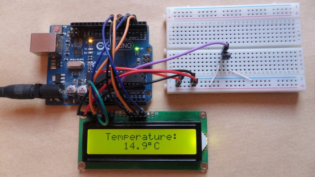
This article shows the interfacing of the Arduino with LM35 analog temperature sensor. The measured temperature value will be displayed on 16×2 LCD screen.
About the LM35 temperature sensor:
The LM35 temperature sensor is a three pin device (VCC, OUT and GND) with an output voltage linearly related to Centigrade temperature. Since the LM35 output varies with dependent to the temperature, we need an ADC (Analog-to-Digital Converter) module to measure this voltage.
The LM35 output has a linear scale factor of +10mV/°C which means the following:
If the output voltage = 10mV —> temperature = 1°C
If the output voltage = 100mV —> temperature = 10°C
If the output voltage = 200mV —> temperature = 20°C
If the output voltage = 370mV —> temperature = 37°C
and so on.
LM35 Futures (from datasheet):
- Calibrated Directly in ° Celsius (Centigrade)
- Linear + 10 mV/°C Scale Factor
- 0.5°C Ensured Accuracy (at +25°C)
- Rated for Full −55°C to +150°C Range
- Suitable for Remote Applications
- Low Cost Due to Wafer-Level Trimming
- Operates from 4 to 30 V
- Less than 60-μA Current Drain
- Low Self-Heating, 0.08°C in Still Air
- Nonlinearity Only ±¼°C Typical
- Low Impedance Output, 0.1 Ω for 1 mA Load
The ADC module converts analog data into digital data. The Arduino UNO board microcontroller (ATmega328P) has a 10-bit ADC module and a built-in fixed voltage reference of 1.1V. With the fixed voltage reference we get approximately an exact result. Normally negative and positive references of the ADC module are VSS and VDD respectively, but VDD is not exactly equal to 5.00V and here we should use the fixed voltage reference as a positive reference of the ADC module. Also, the output of the LM35 varies between 0 and +1V which means with VDD as positive reference we’re wasting 80% of the possible range, with the 1.1V reference we will get approximately the highest resolution.
Hardware Required:
- Arduino board
- LM35 temperature sensor — datasheet
- 16×2 LCD screen
- 10K ohm variable resistor
- Breadboard
- Jumper wires
Arduino + LM35 sensor circuit:
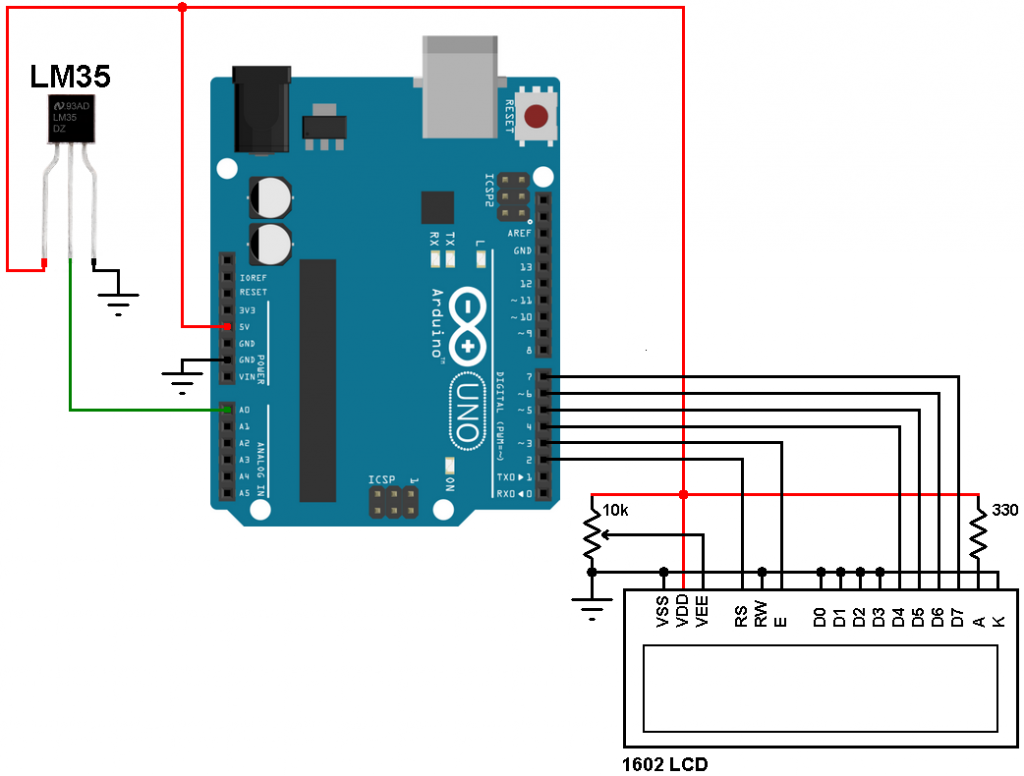
The output of the LM35 sensor is connected to the Arduino uno analog channel 0 (A0) pin.
Arduino + LM35 code:
Reading voltage quantity using the ADC gives us a number between 0 and 1023 (10-bit resolution), 0V is represented by 0 and 1.1V is represented by 1023 (ADC positive reference is 1.1V) . Converting back the ADC digital value is easy, we can use the following equation for that conversion:
Voltage (in Volts) = ADC reading * 1.1 / 1023
Multiplying the previous result by 100 (LM35 scale factor is 10mV/°C = 0.01V/°C) gives the actual temperature:
Temperature( °C) = ADC reading * 0.1075 , or
Temperature( °C) = ADC reading / 9.3
where: 0.1075 = 100 * 1.1 / 1023 and 9.3 = 1 / 0.1075
To use the internal 1.1V reference I used the command: analogReference(INTERNAL);
I used the command sprintf(text, “%3u.%1u%cC”, (int)temp, (int)(temp*10)%10, 223); to store the temperature value (float number) in character variable text with the degree symbol and the letter C ( °C). Here the only one number after the point is used.
%3u is related with (int)temp and it means print the integer number of temp with 3 numbers max (without the point)
. : is the displayed point
%1u is related with (int)(temp*10)%10 and it means print one number after the floating point.
%c is related with 223 and it is for the degree symbol (°) where c is referred to character.
C : is letter
The complete code is the one below.
1 2 3 4 5 6 7 8 9 10 11 12 13 14 15 16 17 18 19 20 21 22 23 24 25 26 | // Arduino interface with LM35 temperature sensor // include LCD library code #include <LiquidCrystal.h> #define LM35_pin 0 // LM35 output pin is connected to Arduino A0 pin // LCD module connections (RS, E, D4, D5, D6, D7) LiquidCrystal lcd(2, 3, 4, 5, 6, 7); void setup() { // set up the LCD's number of columns and rows lcd.begin(16, 2); lcd.setCursor(2, 0); lcd.print("Temperature:"); analogReference(INTERNAL); } float temp; char text[8]; void loop() { delay(1000); // Wait 1s between readings temp = analogRead(LM35_pin) / 9.3; // Read analog voltage and convert it to °C ( 9.3 = 1023/(1.1*100) ) sprintf(text, "%3u.%1u%cC", (int)temp, (int)(temp*10)%10, 223); lcd.setCursor(3, 1); lcd.print(text); } |
Discover more from Simple Circuit
Subscribe to get the latest posts sent to your email.


