After the decoding of an infrared remote control which uses RC5 protocol, now I’m going to decode a remote control uses NEC protocol (this example works with both NEC and extended NEC remote controls). Arduino RC5 decoder topic link:
Arduino RC5 IR remote control decoder
About the NEC protocol:
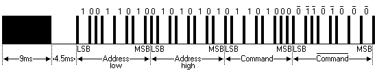
The complete extended NEC protocol message is started by 9ms burst followed by 4.5ms space which is then followed by the Address and Command. The address is 16-bit length and the command is transmitted twice (8 bits + 8 bits) where in the second time all bits are inverted and can be used for verification of the received message. The following drawing shows an extended NEC message example.
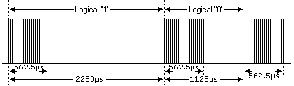
The NEC protocol uses pulse distance encoding of the bits. Each pulse is a 562.5µs long with carrier frequency of 38KHz. Logic bits are transmitted as follows:
Logic 0: 562.5µs pulse burst followed by 562.5µs space, with a total transmit time of 1125µs (562.5 x 2).
Logic 1: a 562.5µs pulse burst followed by a 1687.5µs (562.5 x 3) space, with a total transmit time of 2250µs (562.5 x 4).
Components Required:
- Arduino board
- IR remote control with NEC protocol
- 16×2 LCD screen
- IR receiver
- 47µF capacitor
- 10K ohm variable resistor
- 330 ohm resistor
- Protoboard
- Jumper wires
Arduino NEC protocol decoder circuit:
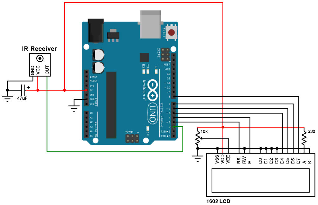
Arduino remote control decoder circuit schematic is shows below.
Arduino NEC remote control decoder code:
Note that there is no remote control library used in this example. The software is fully based on hardware interrupts.
The IR receiver output is logic high at idle state (or while the remote control sends a space) and when it receives a burst it changes the output to logic low.
The message of the NEC protocol is 32-bit long, address (16 bits), command (8 bits), and inverted command (8 bits). Before the previous 32 bits there is 9ms burst and 4.5ms space.
A logic 1 is represented by 562.5µs burst and 562.5µs space (total of 1125µs) and a logic 0 is represented by 562.5µs burst and 1687.5µs space (total of 2250µs).
Keep in mind that the IR receiver output is always inverted.
I used Timer1 module to measure pulses and spaces widths, it is configured so that is increments by 2 every 1 us (1/8 prescaler).
The interval [ 9500µs, 8500µs ] is used for the 9ms pulse and for the 4.5ms space the interval
[ 5000µs, 4000µs ] is used.
The 562.5µs pulse is checked with the interval [ 700µs, 400µs ] .
For the 562.5µs or 1687.5µs space I used the interval [ 1800µs, 400µs ], and to know if its a short or long space I used a length of 1000µs.
In Timer ticks:
[ 9500µs, 8500µs ] = [ 19000 , 17000 ] ticks
[ 5000µs, 4000µs ] = [ 10000 , 8000 ] ticks
[ 700µs, 400µs ] = [ 1400 , 800 ] ticks
[ 1800µs, 400µs ] = [3600 , 800 ] ticks
The output of the IR receiver is connected to the external interrupt INT0 pin (Arduino pin #2) and every change in the pin status generates an interrupt and Timer1 starts calculating, Timer1 value will be used in the next interrupt, this means Timer1 calculates the time between two interrupts which is pulse time or space time. Also, Timer1 interrupt is used to reset the decoding process in case of very high pulse or space.
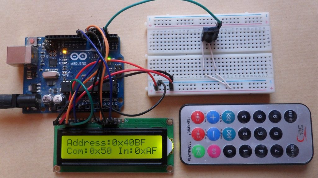
The decoding results are displayed on 1602 LCD screen.
1 2 3 4 5 6 7 8 9 10 11 12 13 14 15 16 17 18 19 20 21 22 23 24 25 26 27 28 29 30 31 32 33 34 35 36 37 38 39 40 41 42 43 44 45 46 47 48 49 50 51 52 53 54 55 56 57 58 59 60 61 62 63 64 65 66 67 68 69 70 71 72 73 74 75 76 77 78 79 80 81 82 83 84 85 86 87 88 89 90 91 92 93 94 95 96 97 98 99 100 101 102 103 104 105 106 107 108 109 110 111 112 | // Arduino NEC Protocol IR remote control decoder // include LCD library code #include <LiquidCrystal.h> // LCD module connection (RS, E, D4, D5, D6, D7) LiquidCrystal lcd(3, 4, 5, 6, 7, 8); char text[5]; boolean nec_ok = 0; byte i, nec_state = 0, command, inv_command; unsigned int address; unsigned long nec_code; void setup() { // set up the LCD's number of columns and rows lcd.begin(16, 2); lcd.setCursor(0, 0); lcd.print("Address:0x0000"); lcd.setCursor(0, 1); lcd.print("Com:0x00 In:0x00"); // Timer1 module configuration TCCR1A = 0; TCCR1B = 0; // Disable Timer1 module TCNT1 = 0; // Set Timer1 preload value to 0 (reset) TIMSK1 = 1; // enable Timer1 overflow interrupt attachInterrupt(0, remote_read, CHANGE); // Enable external interrupt (INT0) } void remote_read() { unsigned int timer_value; if(nec_state != 0){ timer_value = TCNT1; // Store Timer1 value TCNT1 = 0; // Reset Timer1 } switch(nec_state){ case 0 : // Start receiving IR data (we're at the beginning of 9ms pulse) TCNT1 = 0; // Reset Timer1 TCCR1B = 2; // Enable Timer1 module with 1/8 prescaler ( 2 ticks every 1 us) nec_state = 1; // Next state: end of 9ms pulse (start of 4.5ms space) i = 0; return; case 1 : // End of 9ms pulse if((timer_value > 19000) || (timer_value < 17000)){ // Invalid interval ==> stop decoding and reset nec_state = 0; // Reset decoding process TCCR1B = 0; // Disable Timer1 module } else nec_state = 2; // Next state: end of 4.5ms space (start of 562µs pulse) return; case 2 : // End of 4.5ms space if((timer_value > 10000) || (timer_value < 8000)){ nec_state = 0; // Reset decoding process TCCR1B = 0; // Disable Timer1 module } else nec_state = 3; // Next state: end of 562µs pulse (start of 562µs or 1687µs space) return; case 3 : // End of 562µs pulse if((timer_value > 1400) || (timer_value < 800)){ // Invalid interval ==> stop decoding and reset TCCR1B = 0; // Disable Timer1 module nec_state = 0; // Reset decoding process } else nec_state = 4; // Next state: end of 562µs or 1687µs space return; case 4 : // End of 562µs or 1687µs space if((timer_value > 3600) || (timer_value < 800)){ // Time interval invalid ==> stop decoding TCCR1B = 0; // Disable Timer1 module nec_state = 0; // Reset decoding process return; } if( timer_value > 2000) // If space width > 1ms (short space) bitSet(nec_code, (31 - i)); // Write 1 to bit (31 - i) else // If space width < 1ms (long space) bitClear(nec_code, (31 - i)); // Write 0 to bit (31 - i) i++; if(i > 31){ // If all bits are received nec_ok = 1; // Decoding process OK detachInterrupt(0); // Disable external interrupt (INT0) return; } nec_state = 3; // Next state: end of 562µs pulse (start of 562µs or 1687µs space) } } ISR(TIMER1_OVF_vect) { // Timer1 interrupt service routine (ISR) nec_state = 0; // Reset decoding process TCCR1B = 0; // Disable Timer1 module } void loop() { if(nec_ok){ // If the mcu receives NEC message with successful nec_ok = 0; // Reset decoding process nec_state = 0; TCCR1B = 0; // Disable Timer1 module address = nec_code >> 16; command = nec_code >> 8; inv_command = nec_code; sprintf(text, "%04X", address); lcd.setCursor(10, 0); lcd.print(text); // Display address in hex format sprintf(text, "%02X", command); lcd.setCursor(6, 1); lcd.print(text); // Display command in hex format sprintf(text, "%02X", inv_command); lcd.setCursor(14, 1); lcd.print(text); // Display inverted command in hex format attachInterrupt(0, remote_read, CHANGE); // Enable external interrupt (INT0) } } |
Finally I made a small video shows how this project works in hardware circuit:
Reference:
http://www.sbprojects.com/
Discover more from Simple Circuit
Subscribe to get the latest posts sent to your email.


can you write a code for esp32?
How can I print all the values on serial monitor?
void setup() {
Serial.begin(9600); // begin serial communication with a baud rate of 9600
After in :
void loop() {
Serial.println(text);
Serial.println(“%04X”);
Serial.println(address);
Serial.println(text);
…..
}
Serial.println(“%02X”);
Serial.println(command);
Serial.println(text);
Serial.println(“%02X”);
Serial.println(inv_command);
Congratulations! What a perfect IR decoder software: small, good working and instructive.
I built it today into my Si4735 radio project and within 3 hours the troubles with IRlib2 vanished. Machine code size shrunk by 3k bytes as well.
However, there is one small bug in Your Arduino circuit:
The 47uF capacitor in parallel to the IR receiver IC is quite useless until You put a 47 Ohm resistor into the 5V line between IR receiver IC and the Arduino. You may omit the capacitor entirely, if the wires are not too long.
The software is robust enough to remove any erroneous impulses.
Kind regards,
Herbert