This topic shows how did I build a simple remote controlled DC motor (speed and direction of rotation) using an Arduino UNO board and an IR remote control. I used Car MP3 IR remote control which uses NEC protocol and a 12V DC motor.
In the previous post I made a DC motor control circuit using Arduino where a potentiometer was used to control the speed and a pushbutton to control the rotation direction, project link is below:
Arduino DC motor speed and direction control with L293D
Also, I built a decoder circuit for IR remote control with NEC protocol using Arduino because first we’ve to decode our remote control in order to know button codes (to be placed in the software code):
Arduino NEC IR remote control decoder
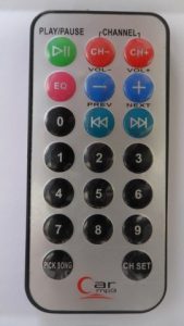
So before you start you have to know your remote control codes, for me I used the remote control shown below, it’s Car MP3 remote control but be careful some other Car MP3 remote controls do not have the same button codes, the best way to find these codes is through decoding it.
In this project I used 3 buttons and I chose: 1, 2 and 3. Button codes (in hexadecimal format) and functions are shown in the table below (NEC remote control code is 32-bit long):
| Button Number | Function | Code |
|---|---|---|
| 1 | Change direction | 0x40BF30CF |
| 2 | Speed down | 0x40BFB04F |
| 3 | Speed up | 0x40BF708F |
Components Required:
- Arduino UNO board —> ATmega328P datasheet
- L293D motor driver IC —> datasheet
- 12V DC motor
- IR remote control (NEC protocol)
- IR receiver
- 47 uF capacitor
- 12V source
- Breadboard
- Jumper wires
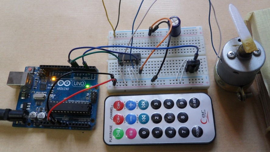
Arduino remote controlled DC motor circuit:
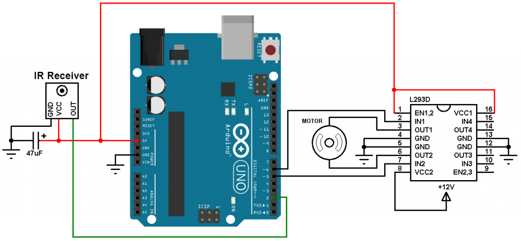
Project circuit schematic diagram is shown below.
The IR receiver is used to receive IR signal comes from the remote control, it has 3 pins: GND, VCC and OUT. It is supplied with 5V which comes from the Arduino board and its output pin is connected to Arduino uno pin 2.
The L293D is supplied with 2 different sources, the first one (VCC1) is +5V and it comes from the Arduino boards, and the 2nd one (VCC2) is +12V which is the same as motor nominal voltage.
Arduino remote controlled DC motor code:
The code below doesn’t use any library for the remote control, it is based on hardware interrupt-on-change on the Arduino uno pin 2.
The message of the NEC protocol is 32-bit long, the code is similar to the one which I used in the decoding project except that I added repeat code detection for buttons 2 (0x40BFB04F) and 3 (0x40BF708F).
I used Timer1 module to measure pulses and spaces widths, it is configured so that is increments by 2 every 1 us (1/8 prescaler).
1 2 3 4 5 6 7 8 9 10 11 12 13 14 15 16 17 18 19 20 21 22 23 24 25 26 27 28 29 30 31 32 33 34 35 36 37 38 39 40 41 42 43 44 45 46 47 48 49 50 51 52 53 54 55 56 57 58 59 60 61 62 63 64 65 66 67 68 69 70 71 72 73 74 75 76 77 78 79 80 81 82 83 84 85 86 87 88 89 90 91 92 93 94 95 96 97 98 99 100 101 102 103 104 105 106 107 108 109 110 111 112 113 114 115 116 117 | // Arduino remote controlled DC motor (speed and direction control) // NEC IR remote control is used (Car MP3) #define pwm1 5 #define pwm2 6 boolean nec_ok = 0, motor_dir = 0, repeated = 0; byte i, nec_state = 0, duty_cycle = 0; unsigned long nec_code; void setup() { pinMode(pwm1, OUTPUT); pinMode(pwm2, OUTPUT); // Timer1 module configuration TCCR1A = 0; TCCR1B = 0; // Disable Timer1 module TCNT1 = 0; // Set Timer1 preload value to 0 (reset) TIMSK1 = 1; // enable Timer1 overflow interrupt attachInterrupt(0, remote_read, CHANGE); // Enable external interrupt (INT0) } void remote_read() { unsigned int timer_value; if(nec_state != 0){ timer_value = TCNT1; // Store Timer1 value TCNT1 = 0; // Reset Timer1 } switch(nec_state){ case 0 : // Start receiving IR data (we're at the beginning of 9ms pulse) TCNT1 = 0; // Reset Timer1 TCCR1B = 2; // Enable Timer1 module with 1/8 prescaler ( 2 ticks every 1 us) nec_state = 1; // Next state: end of 9ms pulse (start of 4.5ms space) i = 0; return; case 1 : // End of 9ms pulse if((timer_value > 19000) || (timer_value < 17000)){ // Invalid interval ==> stop decoding and reset nec_state = 0; // Reset decoding process TCCR1B = 0; // Disable Timer1 module } else nec_state = 2; // Next state: end of 4.5ms space (start of 562µs pulse) return; case 2 : // End of 4.5ms space if((timer_value > 10000) || (timer_value < 3000)){ nec_state = 0; // Reset decoding process TCCR1B = 0; // Disable Timer1 module } else{ nec_state = 3; // Next state: end of 562µs pulse (start of 562µs or 1687µs space) if(timer_value < 6000) // Check if previous code is repeated repeated = 1; } return; case 3 : // End of 562µs pulse if((timer_value > 1400) || (timer_value < 800)){ // Invalid interval ==> stop decoding and reset TCCR1B = 0; // Disable Timer1 module nec_state = 0; // Reset decoding process } else { // Check if the repeated code is for button 2 or 3 if(repeated && (nec_code == 0x40BFB04F || nec_code == 0x40BF708F)){ repeated = 0; nec_ok = 1; // Decoding process is finished with success detachInterrupt(0); // Disable external interrupt (INT0) } else nec_state = 4; // Next state: end of 562µs or 1687µs space } return; case 4 : // End of 562µs or 1687µs space if((timer_value > 3600) || (timer_value < 800)){ // Time interval invalid ==> stop decoding TCCR1B = 0; // Disable Timer1 module nec_state = 0; // Reset decoding process return; } if( timer_value > 2000) // If space width > 1ms (short space) bitSet(nec_code, (31 - i)); // Write 1 to bit (31 - i) else // If space width < 1ms (long space) bitClear(nec_code, (31 - i)); // Write 0 to bit (31 - i) i++; if(i > 31){ // If all bits are received nec_ok = 1; // Decoding process OK detachInterrupt(0); // Disable external interrupt (INT0) return; } nec_state = 3; // Next state: end of 562µs pulse (start of 562µs or 1687µs space) } } ISR(TIMER1_OVF_vect) { // Timer1 interrupt service routine (ISR) nec_state = 0; // Reset decoding process TCCR1B = 0; // Disable Timer1 module } void loop() { if(nec_ok) { nec_ok = 0; // Reset decoding process nec_state = 0; TCCR1B = 0; // Disable Timer1 module if(nec_code == 0x40BF30CF){ // If button 1 is pressed (change motor direction of rotation) motor_dir = !motor_dir; // Toggle direction variable if(motor_dir) digitalWrite(pwm2, 0); else digitalWrite(pwm1, 0); } if(nec_code == 0x40BF708F && duty_cycle < 255) // If button 3 is pressed (increase motor speed) duty_cycle++; if(nec_code == 0x40BFB04F && duty_cycle > 0) // If button 2 is pressed (decrease motor speed) duty_cycle--; if(motor_dir) analogWrite(pwm1, duty_cycle); else analogWrite(pwm2, duty_cycle); attachInterrupt(0, remote_read, CHANGE); // Enable external interrupt (INT0) } } |
Finally, the video below shows a simple hardware circuit of the project:
Discover more from Simple Circuit
Subscribe to get the latest posts sent to your email.


English please, no one understands your stupid languages in the comments
Always the same thing. Never works de scketchs,
Con tantos controles remotos y tuvo que usar un NEC, por mas que he intentado bno se pude.
Can the aystem be able to retain the last settings paraneters after power went off? If no can you pls add such functions to the project so that once the system is switched off and on it will continue from where it was before power went off pls i need such operation for my project
mohon designkan buat sy beli. buat pengaman pintu kamar kos dengan palang kayu seperti rumah kuno. paki motor dc, gearbox dan remote control mini masuk saku.
terima aksih