This topic shows how to connect Arduino UNO with rotary encoder and 7-segment display. Here the rotary encoder is an input device and the 7-segment display is an output device.
The 7-segment display prints the values of the rotary encoder (positive or negative) on 4 digits where the first digit (most left) is used for the minus sign ( -).
To see how to connect Arduino with 7-segment display visit the following post:
Interfacing Arduino with 7-segment display | 4-Digit counter example
To see how the rotary encoder works and how to interface it with Arduino in order to control a DC motor speed, take a look at the project below:
DC Motor control with rotary encoder and Arduino
Parts Required:
- Arduino UNO board —> ATmega328P datasheet
- 4-Digit common anode 7-segment display
- 4 x PNP transistor (2SA1015, 2S9015, 2N3906 …)
- Rotary encoder
- 7 x 100 ohm resistor
- 4 x 4.7k ohm resistor
- Breadboard
- Jumper wires
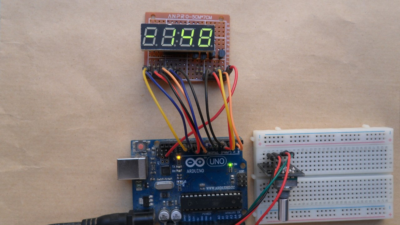
Arduino with rotary encoder and 7-segment display circuit:
The image below shows example circuit schematic diagram.
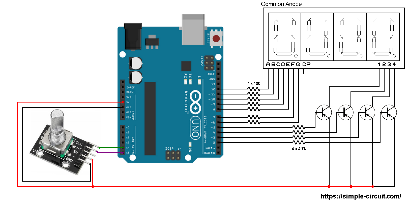
The rotary encoder board has 5 pins: GND, + , SW, DT (pin B or data pin) and CLK (pin A or clock pin) where:
GND is connected to Arduino GND pin
+ is connected to Arduino 5V pin
SW is push button pin, not used in this example
DT is connected to Arduino analog pin 5 (A5)
CLK is connected to Arduino analog pin 4 (A4)
The 4 transistors are of the same type (PNP).
Arduino with rotary encoder and 7 segment display code:
The Arduino code below doesn’t use any library for the 7-segment display.
The rotary encoder pin A (CLK) and pin B (DT) are connected to Arduino UNO pins A4 and A5 respectively. Both pins can be used to interrupt the Arduino microcontroller (ATmega328P) whenever there is a change in the state of at least one pin. The following lines are used to enable interrupt-on-change for pins A4 (PCINT12) and A5 (PCINT13):
1 2 3 | // pin change interrupt configuration PCICR = 2; // enable pin change interrupt for pins PCINT14..8 (Arduino A0 to A5) PCMSK1 = 0x30; // enable pin change interrupt for pins PCINT12 & PCINT13 (Arduino A4 & A5) |
Since the 4 digits are multiplexed we need to refresh the display very quickly (display one digit at a time, others are off). For that I used Timer1 module interrupt with the following configuration:
1 2 3 4 5 | // Timer1 module overflow interrupt configuration TCCR1A = 0; TCCR1B = 1; // enable Timer1 with prescaler = 1 ( 16 ticks each 1 µs) TCNT1 = 0; // set Timer1 preload value to 0 (reset) TIMSK1 = 1; // enable Timer1 overflow interrupt |
With the above configuration Timer1 module overflows every 4096 microseconds (4096 = 65536/16).
Note that Timer1 module is 16-bit timer, prescaler = 1 (TCCR1B = 1) and Arduino UNO clock = 16MHz.
Full Arduino code:
1 2 3 4 5 6 7 8 9 10 11 12 13 14 15 16 17 18 19 20 21 22 23 24 25 26 27 28 29 30 31 32 33 34 35 36 37 38 39 40 41 42 43 44 45 46 47 48 49 50 51 52 53 54 55 56 57 58 59 60 61 62 63 64 65 66 67 68 69 70 71 72 73 74 75 76 77 78 79 80 81 82 83 84 85 86 87 88 89 90 91 92 93 94 95 96 97 98 99 100 101 102 103 104 105 106 107 108 109 110 111 112 113 114 115 116 117 118 119 120 121 122 123 124 125 126 127 128 129 130 131 132 133 134 135 136 137 138 139 140 141 142 143 144 145 146 147 148 149 150 151 152 153 154 155 156 157 158 159 160 161 162 163 164 165 166 167 168 169 170 171 172 173 174 175 176 177 178 179 180 181 182 183 184 185 186 187 188 189 190 191 192 193 194 195 196 197 198 199 200 201 202 203 204 205 206 207 208 209 210 211 212 213 214 215 216 217 218 219 220 221 222 223 224 225 226 227 228 229 230 231 232 233 234 235 236 237 238 239 240 241 242 243 244 245 246 247 248 249 250 251 252 253 | /* * Interfacing Arduino with common anode 7-segment display. * Print rotary encoder values on 4-digit 7-segment display. * This is a free software with NO WARRANTY. * http://simple-circuit.com/ */ // segment pin definitions #define SegA 12 #define SegB 11 #define SegC 10 #define SegD 9 #define SegE 8 #define SegF 7 #define SegG 6 // common pins of the four digits definitions #define Dig1 5 #define Dig2 4 #define Dig3 3 #define Dig4 2 // variable declarations byte current_digit, last_read; int8_t quad = 0, change; int enc_value = 0; void setup() { pinMode(SegA, OUTPUT); pinMode(SegB, OUTPUT); pinMode(SegC, OUTPUT); pinMode(SegD, OUTPUT); pinMode(SegE, OUTPUT); pinMode(SegF, OUTPUT); pinMode(SegG, OUTPUT); pinMode(Dig1, OUTPUT); pinMode(Dig2, OUTPUT); pinMode(Dig3, OUTPUT); pinMode(Dig4, OUTPUT); pinMode(A4, INPUT_PULLUP); pinMode(A5, INPUT_PULLUP); last_read = digitalRead(A5) << 1 | digitalRead(A4); disp_off(); // turn off the display // Timer1 module overflow interrupt configuration TCCR1A = 0; TCCR1B = 1; // enable Timer1 with prescaler = 1 ( 16 ticks each 1 µs) TCNT1 = 0; // set Timer1 preload value to 0 (reset) TIMSK1 = 1; // enable Timer1 overflow interrupt // pin change interrupt configuration PCICR = 2; // enable pin change interrupt for pins PCINT14..8 (Arduino A0 to A5) PCMSK1 = 0x30; // enable pin change interrupt for pins PCINT12 & PCINT13 (Arduino A4 & A5) } ISR(TIMER1_OVF_vect) // Timer1 interrupt service routine (ISR) { disp_off(); // turn off the display uint16_t abs_value = abs(enc_value); // abs: absolute value switch (current_digit) { case 1: if(enc_value < 0) // if negative value { // print minus sign (-) on digit 1 (most left digit) disp(10); // prepare to display digit 1 digitalWrite(Dig1, LOW); // turn on digit 1 } break; case 2: disp( (abs_value / 100) % 10); // prepare to display digit 2 digitalWrite(Dig2, LOW); // turn on digit 2 break; case 3: disp( (abs_value / 10) % 10); // prepare to display digit 3 digitalWrite(Dig3, LOW); // turn on digit 3 break; case 4: disp(abs_value % 10); // prepare to display digit 4 (most right) digitalWrite(Dig4, LOW); // turn on digit 4 } current_digit = (current_digit % 4) + 1; } ISR (PCINT1_vect) // ISR for Arduino A4 (PCINT12) and A5 (PCINT13) pins { uint8_t encoderRead = 0; encoderRead = digitalRead(A5) << 1 | digitalRead(A4); if(encoderRead == last_read) return; if(bitRead(encoderRead, 0) == bitRead(last_read, 1)) quad -= 1; else quad += 1; last_read = encoderRead; } int8_t EncoderGet(void) { int8_t val = 0; while(quad >= 4){ val += 1; quad -= 4; } while(quad <= -4){ val -= 1; quad += 4; } return val; } // main loop void loop() { change = EncoderGet(); if(change) enc_value += change; delay(100); // wait 100 milliseconds } void disp(byte number) { switch (number) { case 0: // print 0 digitalWrite(SegA, LOW); digitalWrite(SegB, LOW); digitalWrite(SegC, LOW); digitalWrite(SegD, LOW); digitalWrite(SegE, LOW); digitalWrite(SegF, LOW); digitalWrite(SegG, HIGH); break; case 1: // print 1 digitalWrite(SegA, HIGH); digitalWrite(SegB, LOW); digitalWrite(SegC, LOW); digitalWrite(SegD, HIGH); digitalWrite(SegE, HIGH); digitalWrite(SegF, HIGH); digitalWrite(SegG, HIGH); break; case 2: // print 2 digitalWrite(SegA, LOW); digitalWrite(SegB, LOW); digitalWrite(SegC, HIGH); digitalWrite(SegD, LOW); digitalWrite(SegE, LOW); digitalWrite(SegF, HIGH); digitalWrite(SegG, LOW); break; case 3: // print 3 digitalWrite(SegA, LOW); digitalWrite(SegB, LOW); digitalWrite(SegC, LOW); digitalWrite(SegD, LOW); digitalWrite(SegE, HIGH); digitalWrite(SegF, HIGH); digitalWrite(SegG, LOW); break; case 4: // print 4 digitalWrite(SegA, HIGH); digitalWrite(SegB, LOW); digitalWrite(SegC, LOW); digitalWrite(SegD, HIGH); digitalWrite(SegE, HIGH); digitalWrite(SegF, LOW); digitalWrite(SegG, LOW); break; case 5: // print 5 digitalWrite(SegA, LOW); digitalWrite(SegB, HIGH); digitalWrite(SegC, LOW); digitalWrite(SegD, LOW); digitalWrite(SegE, HIGH); digitalWrite(SegF, LOW); digitalWrite(SegG, LOW); break; case 6: // print 6 digitalWrite(SegA, LOW); digitalWrite(SegB, HIGH); digitalWrite(SegC, LOW); digitalWrite(SegD, LOW); digitalWrite(SegE, LOW); digitalWrite(SegF, LOW); digitalWrite(SegG, LOW); break; case 7: // print 7 digitalWrite(SegA, LOW); digitalWrite(SegB, LOW); digitalWrite(SegC, LOW); digitalWrite(SegD, HIGH); digitalWrite(SegE, HIGH); digitalWrite(SegF, HIGH); digitalWrite(SegG, HIGH); break; case 8: // print 8 digitalWrite(SegA, LOW); digitalWrite(SegB, LOW); digitalWrite(SegC, LOW); digitalWrite(SegD, LOW); digitalWrite(SegE, LOW); digitalWrite(SegF, LOW); digitalWrite(SegG, LOW); break; case 9: // print 9 digitalWrite(SegA, LOW); digitalWrite(SegB, LOW); digitalWrite(SegC, LOW); digitalWrite(SegD, LOW); digitalWrite(SegE, HIGH); digitalWrite(SegF, LOW); digitalWrite(SegG, LOW); break; case 10: // print - digitalWrite(SegA, HIGH); digitalWrite(SegB, HIGH); digitalWrite(SegC, HIGH); digitalWrite(SegD, HIGH); digitalWrite(SegE, HIGH); digitalWrite(SegF, HIGH); digitalWrite(SegG, LOW); } } void disp_off() { digitalWrite(Dig1, HIGH); digitalWrite(Dig2, HIGH); digitalWrite(Dig3, HIGH); digitalWrite(Dig4, HIGH); } // end of code. |
The following small video shows a test circuit of this project:
Discover more from Simple Circuit
Subscribe to get the latest posts sent to your email.


I didn’t get the answer to one question and I’m already asking another: How do I make the colon blink?
What are transistors for, can’t they be dispensed with? Simply use resistors!
Is it possible to use an 8 channel relay on this project?