In this tutorial I’m going to control a DC motor speed and direction of rotation using Arduino uno board, rotary encoder and L293D motor driver chip.
I used the rotary encoder shown below:
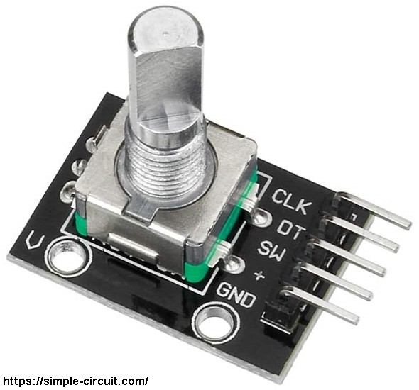
The rotary encoder has 5 pins: GND, + (+5V or 3.3V), SW (push button), DT (pin B) and CLK (pin A).
As an addition to the rotary encoder there is a push button and three pull up resistors for pins SW, DT and CLK of 10K ohm. With the three pull-up resistors, the normal state of each terminal is logic high.
The rotary encoder generates (when rotating) two square waves on pins A (CLK) and B (DT) with 90° out of phase as shown in the figure below:
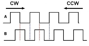
Since the normal state of pin A (CLK) and pin B (DT) are logic high we’ve to detect falling (transition from high to low) of one of them, here pin A is used to detect the movement of the rotary encoder in both directions (falling of pin A signal). Direction of rotation can be detected by knowing the status of pin B, if pin B is logic high this means the direction of rotation is clockwise (CW), and if pin B is logic low this means the direction of rotation is counter clockwise (CCW).
Related projects:
Arduino DC motor speed and direction control with L293D
Arduino based remote controlled DC motor
Arduino DC motor control with joystick and L293D
Hardware Required:
- Arduino UNO board
- Rotary encoder
- DC motor
- L293D motor driver
- Breadboard
- 12V source
- Jumper wires
DC Motor control with rotary encoder and Arduino circuit:
Circuit schematic diagram is shown below.
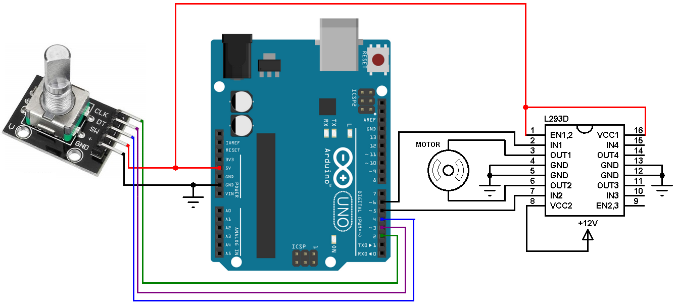
(All grounded terminals are connected, don’t forget the 12V source negative terminal)
The L293D quadruple half-H drivers chip allows us to drive 2 motors in both directions. With two PWM outputs from the Arduino we can easily control the speed as well as the direction of rotation of one DC motor. (PWM: Pulse Width Modulation).
The L293D is supplied with 2 different sources, the first one (VCC1) is +5V which comes from the Arduino boards, and the 2nd one (VCC2) is +12V which is the same as motor nominal voltage. Pin IN1 and pin IN2 are the control pins where:
| IN1 | IN2 | Function |
| L | H | Direction 1 |
| H | L | Direction 2 |
| L | L | Fast motor stop |
| H | H | Fast motor stop |
Arduino pin 5 and pin 6 are PWM signal outputs, at any time there is only 1 active PWM, this allows us to control the direction as well as the speed by varying the duty cycle of the active PWM signal. The active PWM pin decides the motor direction of rotation (one at a time, the other output is logic 0).
The rotary encoder push button terminal is connected to the Arduino pin 4, with this button we can change the direction of rotation of the motor.
DC Motor control with rotary encoder and Arduino code:
The rotary encoder pin A (CLK) and pin B (DT) are connected to Arduino UNO pins 2 and 3 respectively. Both pins can be used to interrupt the Arduino microcontroller (ATmega328P) whenever there is a change in the state of at least one pin. The two interrupts are initialized with the following lines:
1 2 | attachInterrupt(0, encoder_read, CHANGE); attachInterrupt(1, encoder_read, CHANGE); |
Interrupt 0 is for pin 2 and interrupt 1 is for pin 3.
Both interrupts call the function void encoder_read() which is used to read the state of the two rotary encoder pins pin 1 (CLK) and pin B (DT).
Full Arduino code:
1 2 3 4 5 6 7 8 9 10 11 12 13 14 15 16 17 18 19 20 21 22 23 24 25 26 27 28 29 30 31 32 33 34 35 36 37 38 39 40 41 42 43 44 45 46 47 48 49 50 51 52 53 54 55 56 57 58 59 60 61 62 63 64 65 66 67 68 69 70 71 72 73 74 75 76 77 78 79 80 81 82 83 84 85 86 87 88 89 90 91 92 93 94 95 96 97 98 99 100 101 102 103 104 105 106 107 108 109 110 111 112 113 114 115 116 | /* * DC motor speed and direction of rotation control with Arduino * and rotary encoder * This is a free software with NO WARRANTY. * http://simple-circuit.com/ */ #define button 4 // Rotary encoder push-button pin (SW) is connected to Arduino pin 4 #define pwm1 5 // PWM1 output #define pwm2 6 // PWM2 output // variable declarations boolean motor_dir = 0; uint8_t last_read; int8_t quad = 0, change; int16_t motor_speed = 0; void setup() { pinMode(2, INPUT_PULLUP); pinMode(3, INPUT_PULLUP); pinMode(button, INPUT_PULLUP); pinMode(pwm1, OUTPUT); pinMode(pwm2, OUTPUT); last_read = digitalRead(3) << 1 | digitalRead(2); attachInterrupt(0, encoder_read, CHANGE); attachInterrupt(1, encoder_read, CHANGE); } void encoder_read() { uint8_t encoderRead = 0; encoderRead = digitalRead(3) << 1 | digitalRead(2); if(encoderRead == last_read) return; if(bitRead(encoderRead, 0) == bitRead(last_read, 1)) quad -= 1; else quad += 1; last_read = encoderRead; } int8_t EncoderGet(void) { int8_t val = 0; while(quad >= 4){ val += 1; quad -= 4; } while(quad <= -4){ val -= 1; quad += 4; } return val; } bool debounce() { byte count = 0; for(byte l = 0; l < 5; l++) { if (digitalRead(button) == 0) count++; delay(10); } if(count > 2) return 1; else return 0; } void loop() { if(digitalRead(button) == 0) // if Button is pressed if(debounce()) // call debounce function { motor_dir = !motor_dir; // invert direction variable set_speed(motor_speed); while(debounce()); // call debounce function (wait for button to be released) } change = EncoderGet(); if(change){ motor_speed += change; if(motor_speed > 255) motor_speed = 255; if(motor_speed < 0) motor_speed = 0; set_speed(motor_speed); } delay(50); // wait 50 ms } void set_speed(byte pwm_duty) { switch (motor_dir) { case 0: digitalWrite(pwm1, 0); analogWrite(pwm2, motor_speed); break; case 1: digitalWrite(pwm2, 0); analogWrite(pwm1, motor_speed); } } // end of code. |
Here is a simple video of the example:
Discover more from Simple Circuit
Subscribe to get the latest posts sent to your email.


