The brushless dc motor is a three-phase dc motor which requires a controller to power its 3 phases. This controller is called an ESC (Electronic Speed Controller).
This topic shows how to drive a BLDC motor using Arduino where the speed is controlled with a potentiometer.
The brushless dc (BLDC) motor is a 3-phase motor comes in two main types: sensored and sensorless. The sensorless BLDC motor control technique is based on the BEMF (Back Electromotive Force) produced in the stator windings.
In this blog there are many topics show how to control sensored and sensorless brushless DC motors using Arduino and some other PIC microcontrollers.
One of these projects shows how to build a simple ESC using Arduino where the speed of the BLDC motor is controlled with two push buttons.
In this project I’m going to make the same controller but a potentiometer is used instead of the two push buttons.
Related Projects:
The following topic shows more details about the BEMF technique:
Sensorless BLDC motor control with Arduino – DIY ESC
Other BLDC motor project:
Brushless DC motor controller using Arduino and IR2101
In the above two projects, I used the Atmega328P (Arduino UNO microcontroller) internal analog comparator to detect the zero crossing events of the 3 phases, but it’s not a good idea (may give bad results) to use this comparator and the ADC module because they share the same multiplexer. So, I used an external chip which is LM339 quad comparator IC.
Hardware Required:
- Arduino UNO board —-> ATmega328P datasheet
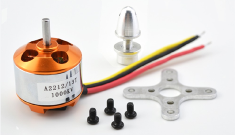
- Brushless DC motor (I’m using A2212/13T 1000KV)
- 6 x 06N03LA N-type mosfet (or equivalent) —-> datasheet
- 3 x IR2101 (or IR2101S) gate driver IC —-> datasheet
- LM339 quad comparator IC —-> datasheet
- 6 x 33k ohm resistor
- 6 x 10k ohm resistor
- 6 x 10 ohm resistor
- 3 x IN4148 diode
- 3 x 10uF capacitor
- 3 x 2.2uF capacitor
- 10k ohm potentiometer
- 12V source
- Breadboard
- Jumper wires
In this project I’m using the motor shown below, it full name is A2212/13T 1000KV:
Brushless dc motor control with Arduino circuit:
The following image shows project circuit schematic diagram.
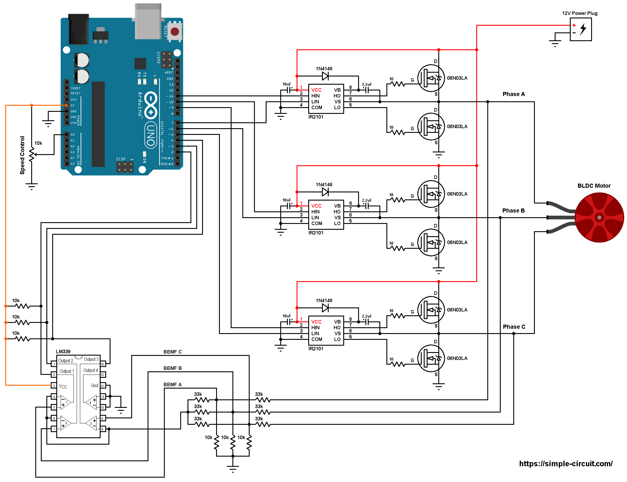
All grounded terminals are connected together.
As mentioned above, the brushless dc motor is a 3-phase motor. In the circuit diagram above the 3 phases are named: Phase A, Phase B and Phase C.
The first three 33k (connected to motor phases) and the three 10k resistors are used as voltage dividers, the other three 33k resistors generate the virtual natural point.
In this project we need 3 comparators to compare the BEMF of each phase with respect to the virtual natural point because we need to detect the zero crossing of each phase, here I used the LM339 quad comparator chip. The virtual point is connected to the inverting input ( – ) of the three comparators as shown in the circuit diagram above. BEMF A is connected to the non-inverting pin ( + ) of comparator number 1, BEMF B is connected to the positive terminal of comparator 2 and BEMF C is connected to the positive terminal of comparator 3. Comparator 4 is not used and its input terminals should be grounded.
As known the comparator output is logic 1 if the non-inverting voltage is greater than the inverting voltage and vice versa.
The LM339 outputs are open collector which means a pull up resistor is needed for each output, for that I used three 10k ohm resistors.
The outputs of the 3 comparators are connected to Arduino pins 2, 3 and 4 respectively for BEMF A, BEMF B and BEMF C.
Arduino UNO pins 2, 3 and 4 are ATmega328P microcontroller external interrupt pins PCINT18, PCINT19 and PCINT20 respectively.
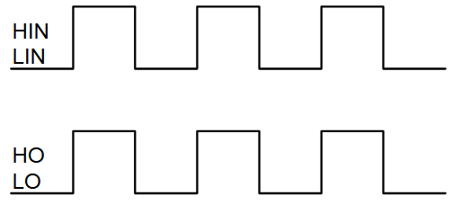
The IR2101 chips are used to control high side and low side mosfets of each phase. The switching between the high side and the low side is done according to the control lines HIN and LIN. The figure below shows input and output timing diagram:
The HIN lines of the three IR2101 are connected to pins 11, 10 and 9 respectively for phase A, phase B and phase C. The Arduino UNO can generate PWM signals on that pins where only high side mosfets are PWMed.
The LIN lines are connected to Arduino pins 7, 6 and 5 respectively for phase A, phase B and phase C.
The 10k potentiometer is used to vary the speed of the BLDC motor, its output is connected to Arduino analog channel 0 (A0).
Brushless dc motor control with Arduino code:
Arduino pins 9, 10 and 11 can generate PWM signals where pin 9 and pin 10 are related to Timer1 module (OC1A and OC1B) and pin 11 is related to Timer2 module (OC2A). Both Timer modules are configured to generate a PWM signal with a frequency of about 31KHz and a resolution of 8 bits. The duty cycles of the PWM signals are updated when the ADC module completes its conversion by writing to registers OCR1A, OCR1B and OCR2A.
Rest of code is described through comments!
1 2 3 4 5 6 7 8 9 10 11 12 13 14 15 16 17 18 19 20 21 22 23 24 25 26 27 28 29 30 31 32 33 34 35 36 37 38 39 40 41 42 43 44 45 46 47 48 49 50 51 52 53 54 55 56 57 58 59 60 61 62 63 64 65 66 67 68 69 70 71 72 73 74 75 76 77 78 79 80 81 82 83 84 85 86 87 88 89 90 91 92 93 94 95 96 97 98 99 100 101 102 103 104 105 106 107 108 109 110 111 112 113 114 115 116 117 118 119 120 121 122 123 124 125 126 127 128 129 130 131 132 133 134 135 136 137 138 139 140 141 142 143 144 145 146 147 148 149 150 151 152 153 154 155 156 157 158 159 160 161 162 163 164 165 166 167 168 169 170 171 172 173 174 175 176 177 178 179 180 181 182 183 184 185 186 187 188 189 190 191 192 193 194 195 196 197 | /* Sensorless brushless DC motor control with Arduino UNO and IR2101 (Arduino DIY ESC). * BLDC motor speed is controlled with a potentiometer connected to A0. * This is a free software with NO WARRANTY. * http://simple-circuit.com/ */ #define PWM_MAX_DUTY 255 #define PWM_MIN_DUTY 50 #define PWM_START_DUTY 100 byte bldc_step = 0, motor_speed, pin_state; void setup() { DDRD |= 0xE0; // configure pins 5, 6 and 7 as outputs PORTD = 0x00; DDRB |= 0x0E; // configure pins 9, 10 and 11 as outputs PORTB = 0x31; // Timer1 module setting: set clock source to clkI/O / 1 (no prescaling) TCCR1A = 0; TCCR1B = 0x01; // Timer2 module setting: set clock source to clkI/O / 1 (no prescaling) TCCR2A = 0; TCCR2B = 0x01; // ADC module configuration ADMUX = 0x60; // configure ADC module and select channel 0 ADCSRA = 0x84; // enable ADC module with 16 division factor (ADC clock = 1MHz) PCICR = EIMSK = 0; // disable all external interrupts pinMode(2, INPUT_PULLUP); pinMode(3, INPUT_PULLUP); pinMode(4, INPUT_PULLUP); } // pin change interrupt 2 (PCINT2) ISR ISR (PCINT2_vect) { if( (PIND & PCMSK2) != pin_state ) return; // BEMF debounce for(byte i = 0; i < 20; i++) { if(bldc_step & 1){ if(PIND & PCMSK2) i -= 1; } else { if(!(PIND & PCMSK2)) i -= 1; } } bldc_move(); bldc_step++; bldc_step %= 6; } // BLDC motor commutation function void bldc_move() { switch(bldc_step) { case 0: AH_BL(); BEMF_C_FALLING(); break; case 1: AH_CL(); BEMF_B_RISING(); break; case 2: BH_CL(); BEMF_A_FALLING(); break; case 3: BH_AL(); BEMF_C_RISING(); break; case 4: CH_AL(); BEMF_B_FALLING(); break; case 5: CH_BL(); BEMF_A_RISING(); } } void loop() { SET_PWM_DUTY(PWM_START_DUTY); // setup starting PWM with duty cycle = PWM_START_DUTY int i = 5000; // motor start while(i > 100) { delayMicroseconds(i); bldc_move(); bldc_step++; bldc_step %= 6; i = i - 20; } motor_speed = PWM_START_DUTY; PCICR = 4; // enable pin change interrupt for pins PCINT23..16 (Arduino 0 to 7) while(1) { ADCSRA |= 1 << ADSC; // start conversion while(ADCSRA & 0x40); // wait for conversion complete motor_speed = ADCH; // read ADC data (8 bits only) if(motor_speed < PWM_MIN_DUTY) motor_speed = PWM_MIN_DUTY; SET_PWM_DUTY(motor_speed); } } void BEMF_A_RISING() { PCMSK2 = 0x04; // enable Arduino pin 2 (PCINT18) interrupt, others are disabled pin_state = 0x04; } void BEMF_A_FALLING() { PCMSK2 = 0x04; // enable Arduino pin 2 (PCINT18) interrupt, others are disabled pin_state = 0; } void BEMF_B_RISING() { PCMSK2 = 0x08; // enable Arduino pin 3 (PCINT19) interrupt, others are disabled pin_state = 0x08; } void BEMF_B_FALLING() { PCMSK2 = 0x08; // enable Arduino pin 3 (PCINT19) interrupt, others are disabled pin_state = 0; } void BEMF_C_RISING() { PCMSK2 = 0x10; // enable Arduino pin 4 (PCINT20) interrupt, others are disabled pin_state = 0x10; } void BEMF_C_FALLING() { PCMSK2 = 0x10; // enable Arduino pin 4 (PCINT20) interrupt, others are disabled pin_state = 0; } void AH_BL() { PORTD &= ~0xA0; PORTD |= 0x40; TCCR1A = 0; // turn pin 11 (OC2A) PWM ON (pin 9 & pin 10 OFF) TCCR2A = 0x81; // } void AH_CL() { PORTD &= ~0xC0; PORTD |= 0x20; TCCR1A = 0; // turn pin 11 (OC2A) PWM ON (pin 9 & pin 10 OFF) TCCR2A = 0x81; // } void BH_CL() { PORTD &= ~0xC0; PORTD |= 0x20; TCCR2A = 0; // turn pin 10 (OC1B) PWM ON (pin 9 & pin 11 OFF) TCCR1A = 0x21; // } void BH_AL() { PORTD &= ~0x60; PORTD |= 0x80; TCCR2A = 0; // turn pin 10 (OC1B) PWM ON (pin 9 & pin 11 OFF) TCCR1A = 0x21; // } void CH_AL() { PORTD &= ~0x60; PORTD |= 0x80; TCCR2A = 0; // turn pin 9 (OC1A) PWM ON (pin 10 & pin 11 OFF) TCCR1A = 0x81; // } void CH_BL() { PORTD &= ~0xA0; PORTD |= 0x40; TCCR2A = 0; // turn pin 9 (OC1A) PWM ON (pin 10 & pin 11 OFF) TCCR1A = 0x81; // } void SET_PWM_DUTY(byte duty) { OCR1A = duty; // set pin 9 PWM duty cycle OCR1B = duty; // set pin 10 PWM duty cycle OCR2A = duty; // set pin 11 PWM duty cycle } |
The following video shows my simple hardware circuit result:
Discover more from Simple Circuit
Subscribe to get the latest posts sent to your email.


your code is work well- can you make a project using FOC algorithm for sensor less bldc motor
iam using ir2110 driver and irfzz4n mosfet,did the simulation but not working ? is it required to edit the code? kindly help me
The motor just vibrates for like 2 seconds and that’s it. Motor doesn’t spin or shows any sign of life. I have proper connections and used the same components as shown in the schematic. What is the error in the code and can you please give me the correct code?
hi bro,im doing the same project i used ir2110 driver and irfz44n mosfet, did the simulation but not running, do u got it right? can you help me?
Hello. I built the circuit. My problem is that the IR2101 chip of the “B” phase gets hot in 1-2 seconds. The engine won’t start. I checked the connection, the parts are good. Why is not working? Please help!
Can IRFZ44 MOSFETs be used?
How to make CCW
Hemanth you have to add DPDT(Double Pole Double Throw) Switch, it has 6 pins after the correct connection (refer youtube) you’ll get 4 terminals to use. From 4 you have to connect Two terminals to the motor and other remaining 2 to this ESC! You’ll get change in DOR after changing the knob!
plz reply sir
could an Arduino MEGA be used instead of an UNO?
sir can u make project on sensored bldc motor control using pic microcontroller and with 6 pwm using tlp250 based driver circuit. make it asap and reply me sir.
Hi, thank you for your project. I started this project a few weeks ago and finally finished it. It works well. I used same components except MOSFET. I used IR2203 that someone mentioned in the reply. I hope it helps those who are challenging, and I share the news of my success.
it’s IRF or IRL or IR mosfet driver or mosfet bit confusion!
hello bro do you changed the code? im using ir2110 driver and irfz44n mosfet,is it okay? i did the simulation but not working,can u pls help me?
Hi, I have tried both your sensorless bldc control with pushbuttons or potentiometer, but it just doesn’t work. I did double check my circuit ti make sure it is correct. I am using a bldc motor with A2212/10T 1400KV, does that matter? Other than that all the components are the same as you listed. Could you please help?
HI SIR. thank you so much for the project sharing . can you please tell me the maximum current and voltage can be draw from the circuit to the motor ?
I want to modify the code to only deliver pulsed power. The pulse will be set at a finite value, and the frequency must vary up to where it would deliver no higher than a 50% duty cycle. Frequency will go up to the RF range and pulse width will be for example perhaps 10ms. Voltages will be high. Where would I start in the code modification?
Congrats! Great project man! Works great with a 3-ph HDD motor, no center tap. When powered, 90% of the time the motor just wiggled fw and bw, but after modifying the pwm start to 15000, it had enough slow speed cycles to get to full speed in a few seconds. It starts spinning slowly on power-up even if the pot is at 0. Does the circuit need any additional component for protection like schottkys, and where? I have used 100nF caps instead of 2.2uF between VB and VS, and also no caps on the IRF’s supply pins +/-. What’s your recommandation? Thank you in advance!
Excelent projet! I built this and have my BLDC running. I used IR2110 Mosfet drivers and IRF3205 Mosfets, and it works perfectly. I just have two questions
First, what does the “BEMF debounce” section do”? Just checking if the interruption was made by the correct fase zero cross?
And second, I understand by the diagrams shown in the previous project (the one with the two pushbuttons) that when a zero-cross is detected you must wait 30° degrees to shift the phase. Do you do this with this code? If so, which part of the code does this?
I admire your work and would appreciate an answer for these questions. Thanks!
Can you share schematic with ir2110, thanks
Daniel, I am up to the same tricks, high voltage pulses to drive my washing machine motor. I will be driving a 110/220v alternator. I plan on a range of 0-30kc pulses, approaching a 50% duty cycle, using 400vdc pulses. Code needs big changes, limiting the PWM duty cycle, and especially, it has a fixed frequency I haven’t figured out yet. The whole potentiometer function needs to control frequency instead of pwm, while the duty cycle concept gives way to a fixed width pulse, say 10ms… I am using an IRF840 MOSFET, with a range up to a 1000v. Maybe we should collaborate. sampojoe@comcast.net
ok . I will help you soon. I also have a new code and scheme. protection for over voltage, over current, stop, play, reset, failure, etc. I still have to get my pcb in a month and I will let you know if it works ok at 600v
My best equipment will only get me about 400v.
hello. if you can help or guide me. I use in this project ir2104, arduino nano, as 10mega, 2.2k and 68k dividers, IRFP460 for 500 vdc. between the VS of the 3 gate drivers and each phase I put a shotcky diode. I want to use high voltage and high frequency to run the motor of an LG direct drive washing machine. please tell me if I need another code? or what changes must be made to the circuit to work perfectly? will it work like this with the changes I made?
I was able to build the circuit and it works perfectly !! .. I am using Arduino UNO, Ir2101 and I tried different Mosfet and it works perfectly with any of them: IRF3205, W26NM60 and 2SK3570. Thank you so much !
This will help many others, thanks!
Hello Pablo,
Did you made any adjustments in the code with the IRF3205.
Thanks in advance for the feedback.
Hi Petko :
I did not make any adjustments to the code, I used the original code for all mosfets
I have copied the code as it is and tried to simulate it on tinkercad.
After about 1.2 seconds of simulation the outputs just freeze at whatever levels there were at.
Which is also probably why when I connect to the physical arduino board and other components, the motor does not seem to spin. What am I missing? I am surprised there are a few on here who claim that this code worked perfectly.
Please advice. Did you make any changes to the code at all?
Did you get any solution?
can you please tell me on which simulation software i can get better results?
Excuse me but I couldn’t tell you. I don’t know about simulation software
Hi Simple-Cricuit,
I was able to do the project. Thanks for the code and explanation. Can you please explain me the debounce logic used in this code
I used IR2104 and changed the code in AH_BL() and rest, the motor works fine.Can you explain me PIND & PCMSK2 this part so that I can do the necessary changes in Debounce code
I’m using 2104 too. how should I write the code. i’m a beginner I will be glad if you help.
Dear Simple-circuit:
I am working on your project. But when the test run, the engine only spun a few rounds and then stopped and the rheostat didn’t work. You may ask yourself if this project can reverse the BLDC motor, what factors need to change ??
Dear Simple Projects,
Firstly, I must say that you’ve done a great work. Coincidentally, I’m working on a similar project right now and I found your work very helpful. Please, can you upload a Proteus simulation of this work or in any other software? I’ve been struggling with getting the simulation right for weeks now.
I have problems with the simulation that I did in the program.
Sorry, I’ve no simulation file for this project!
Now can I use the source code on the article? I mean, I read some of the comments above about bugs in source code. Have errors in the code have been fixed and updated yet?
Waiting for your response.
Hi Sir! Thanks for the article!
I have a question: If I use a motor operating at a voltage greater than 12V, how will the B-EMF sensor circuit adjust. Do you know any articles or formulas that I can find?
Yes you need to make some modifications to the circuit. Keep in mind that the Arduino UNO board can’t accept more than 5.5V on its input pins!
It’s me again,
I have a question: value PWM_MIN_DUTY = 50 can be set to 0 or not. I mean I want it to start and not spin (RPM = 0 or PWM = 0). After increasing the value from potentiometer, the motor speed starts to rise from 0.
Actually you can’t, because to be able to sense BEMF signals the motor needs to run with sufficient RPM.
You can do that with sensored BLDC motor!
hello Sir,I have a problem with the code, I use the Arduino D1 board, and when I load the software it gives an error.
The code will not work with your board, you’ve to use one with ATmega328P microcontroller!
ok..Thanks..
Hello Sir, I am using this to run a larger bldc motor removed from a washing machine (it ran a fan), it is quite a bit bigger than the motor you used. It does start and run the fan at a good speed and torque, I am using an irl 2110 as a driver and all the signals look good. I do not get any useful speed control .. any ideas of what to look for would be great, also and more importantly is it possible to reverse the motor with this circuit? This is great article and the circuit looks excellent, a good walk through of the design criteria would be helpful. I did find it very susceptible to noise, partly due to the prototype board I added 3 electrolytics and a bunch of other capacitors to ease this. also put diodes on the drive transistor gate resistors .
Hello Sir, can u please tell me an alternative for 06N03LA which I can get on proteus as well?
Can I use it to run a 100 volt BLDC motor? I should change the feedback resistor values? Also will the same code work on that motor as well because I think the starting of motor code needs to be altered?
Hello Sir,
I have a question on it. I am not understand why adding the voltage divider of first 33k and 10k resistors. After added these resistors, the point taking to the positive and negative of the comparator are not equal with the original of phase voltage and neutral voltage, even the ratio is also different. That would affect to the switching moment and the result??
Also one thing about the parallel connect with 10k resistors to the ground, it was also parallel with the motor. There should cause the current through from the motor neutral point to the motor unused phase. That wouldn’t be a problem to the operation??
Thank you for identify my question.
Hello I am using l6234 instead of Ir2021 I also modified the code but motor is only working when I initialize a 3ms delay in ISR. Without that delay my motor start making noise which is not good so could you please help me out what would be the issue and how it could be resolved,
Hi sir. Im trying to run this project using a bldc motor i made from a car alternator. The motor turns for about 10° and then it starts vibrating. Any idea what the problem might be ??? m using a 12v12ah for the motor drive and 15v lab power supply for the gate drivers and irf540 fets. Thanks in advance
I cannot think that you’re giving it enough current unless you’re using a really small alternator. Most modern alternators are rated for at least 1200W, and they don’t work as well in “motor mode” as they do in “alternator mode”.
Dear Simple Projects,
Firstly, I must say that you’ve done a great work. Coincidentally, I’m working on a similar project right now and I found your work very helpful. Please, can you upload a Proteus simulation of this work? I’ve been struggling with getting the simulation right for weeks now. Thank you.
Sorry, there is no Proteus simulation for this project!
Dear Sir, have you ever read this paper:
IEEE TRANSACTIONS ON POWER ELECTRONICS, VOL. 22, NO. 2, MARCH 2007
A New Cost Effective Sensorless Commutation Method for Brushless DC Motors Without
Phase Shift Circuit and Neutral Voltage,
Cheng-Hu Chen and Ming-Yang Cheng, Member, IEEE ?
A more simple sensorless commutation circuit is proposed that not use the motor neutral voltage and can be easily interfaced with hall sensor based commutation circuit.
Thank you for Projects.
Sir…please reply to my question…I have to think complementary ways ,if you say NO…please reply…
hai Vignesh S, are you completed your final year project??
please do response via mail praveenkumar36gct@gmail.com
im also doing now the same project as my final year project.
Sir…please don’t mistake me..I am weak in programming language…would you please explain me ,what are the modifications has to be done in my program to get result from IR2104 Driver IC and external comparator?…
If you don’t have time to explain me about the code..please give me a corrected code for external comparator and IR2104 ICs…. You have much more knowledge in this topic…our staffs also doesn’t know about it…your small help in this project must make it work and help me a lot in my UG grades …..please think about my situation….thanks for every knowledge you put in my mind…you are doing really really great job…..
Sir….please reply to my question..I have to finish my project…
Instead of using IR2101 driver chip,can I use IR2104S.
I have completed the project from your tutorial (http://simple-circuit.com/arduino-sensorless-bldc-motor-controller-esc/)
As you said it gave a bad result.
I have that IR2104S Driver IC,
If I use that driver IC in this external comparator project,can I get a good output?
please explain this project deatails in details.I have so many problems and questions about this project.I am doing this as my final year project.
Please reply as soon as possible…
thanks in advance
Yes you can use the IR2104S but you’ve to do few modifications to the Arduino code, you’ll get a ‘good’ result (with external comparator IC and potentiometer).
Dear Simple-circuit :
You say that ” isn´t a good idea to use this comparator and the ADC module because they share the same multiplexer.(in arduino uno)” .
But now become popular the STM32 using Arduino IDE (for example https://circuitdigest.com/stm32-projects-and-tutorials ) .In STM32 the comparator and the ADC module also share the same multiplexer ?
If I recall correctly, the STM32 doesn’t contain any internal comparators. It’s also vast overkill for a project like this, and it isn’t available in a through-hole package so it’s harder to work with.
Are you sure this code is working properly?
My notices:
I think in CH_BL() function the TCCR1A should be 0x21;
Why DDRD is 0x38? I think it should be 0XE0
If you use external pullup resistor why use it internal in code?
pinMode(2, INPUT_PULLUP);
pinMode(3, INPUT_PULLUP);
pinMode(4, INPUT_PULLUP);
You use also the PORB pullup but I think is not necessary (PORTB = 0x00; //because of internal pullup disabled)
Can you please check it again this is the right and working code?
Yes you’re right the value of DDRD which has to be 0xE0 instead of 0x38 and now it is corrected, thank you.
Secondly, you can disable the internal pull-ups of pins: 2, 3 and 4 since they’ve external ones.
The other thing:
pins 9, 10 and 11 are the high side PWM signals, every time there is only 1 active, register TCCR1A controls pin 9 and pin 10 as follows:
TCCR1A = 0; makes both of them work as any other I/O pin.
TCCR1A = 0x21; enables PWM on pin 10 which is related to OC1B.
TCCR1A = 0x81; enables PWM on pin 9 which is related to OC1A.
The control line of the high side mosfet (HIN) of phase C is connected to Arduino pin 9 and its PWM is enabled when TCCR1A = 0x81.
sir, Are correct all errors can i use this project?
thanks……………..
Hello sir,
I got an error
TCCR2A = 0; // turn pin 9 (OCIA) ( pin 10 & pin 11 off)
I can not understand what is the error.
The Arduino ide say ‘TCCR2A’ was not declared I this scope.
Wht is the scope. Plz help me sir I need the cod plz solve my error
Maybe you’re not using an Arduino UNO or similar board with ATmega328P MCU!
Can this code be used for hub bldc motor which are used in segways or the ebikes which you can stand on it and ride.can those motors be controlled with this code??
Not with the specified MOSFETs!
@Amarton, sir can you help me to complete my project.. tried the above circuit with the give code but it dosen’t work properly.. i quess you have good in this project so,please help me to complete my project sir. pls give ur mail id.. you can reach me out via my mail praveenkumar36gct@gmail.com
Hola. Estuve viendo el circuito y me anima a hacerlo. Tengo arduino nano. Crees que puedo hacerlo igual?. Gracias por compartir Dios te bendiga.
Yes you can use Arduino nano board, it has the same specifications as the uno board.