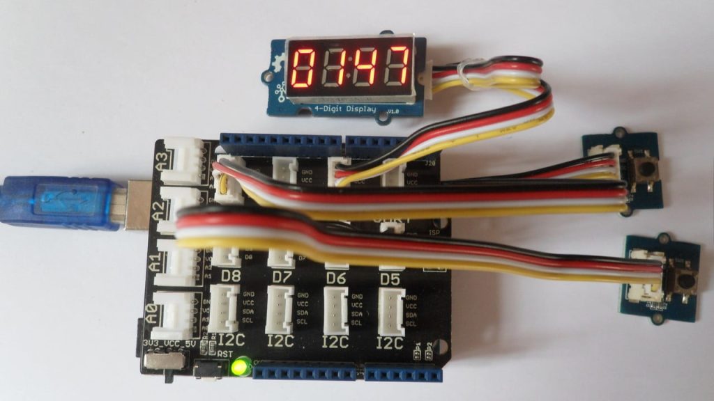
This Arduino project shows how to build a 4-digit digital up/down counter using Seeed Studio Grove 4-digit display. This counter is incremented and decremented using two Grove button modules.
The Grove 4-digit display module is shown below (face):
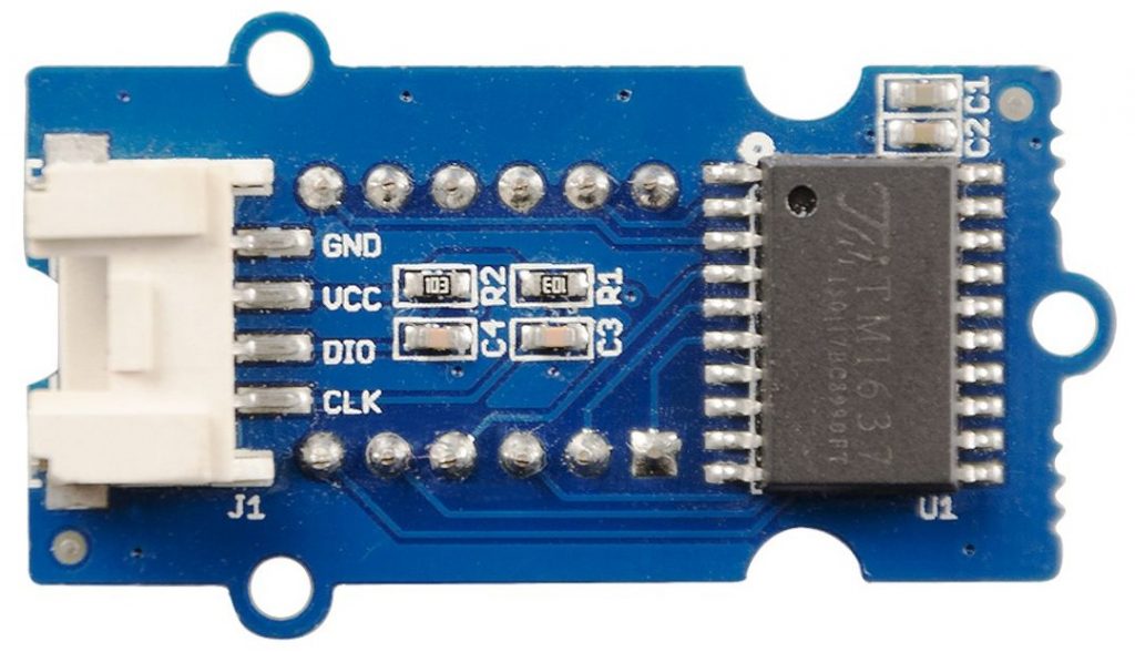
And the following image shows its back:
The Grove 4-digit display module consists of TM1637 integrated circuit (datasheet), 2x10k SMD resistors, 4 SMD capacitors and Grove 4-pin cable socket. SMD: Surface Mounted Device.
With the TM1637 IC, number of pins required by the 4-digit 7-segment display is minimized to 2.
This module supports 3.3V and 5V systems.
This display module is connected to Seeed Studio Base Shield via 4-pin Grove cable, the base shield is an add-on board that directly mounted to the Arduino/Genuino uno board.
The 4-pin cable pins are: GND, VCC, DIO (data input/output) and CLK (clock).
The digital pins DIO and CLK control the displayed content and the brightness of the display.
The displayed number of the digital counter is controlled from 2 Grove button modules connected to the base shield.
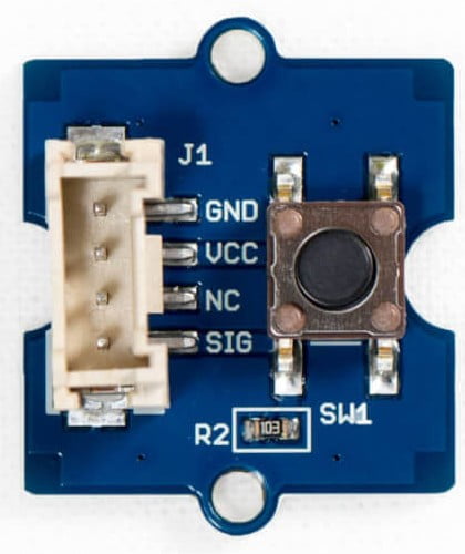
The following image shows the Grove button module:
The button module has a pull down resistor of 10k ohm, if the button is pressed the state of SIG (signal) pin will change from low to high.
Hardware Required:
- Arduino/Genuino UNO board
- Grove base shield —> official page
- Grove 4-digit display —> official page
- 2 x Grove button module —> official page
- 3 x Grove 4-pin cable
Arduino 4-digit counter circuit:
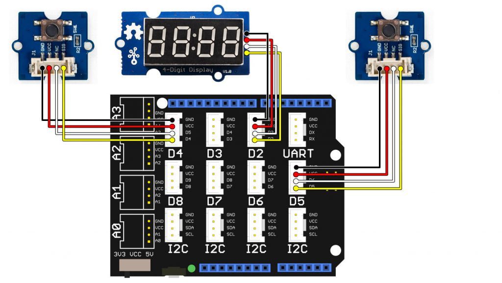
The following image shows the connection of the 3 modules with the Grove base shield where three 4-pin cables are used for the connection between the Grove modules.
Note that the base shield is directly mounted to the Arduino UNO board.
The Grove 4-digit display is connected to base shield port D2 where:
GND pin is connected to Arduino GND,
VCC pin is connected to Arduino +5V pin,
DIO is connected to Arduino digital pin 3,
CLK is connected to Arduino digital pin 2.
The UP button module is connected to base shield port D4 where:
GND pin is connected to Arduino GND,
VCC pin is connected to Arduino +5V pin,
NC (not connected) is not connected pin (using the 4-pin cable it looks as it is connected to base shield D5 pin),
SIG pin is connected to Arduino digital pin 4.
The DOWN button module is connected to base shield port D5 with its SIG pin connected to Arduino digital pin 5.
Arduino 4-digit counter code:
Seeed Studio provides a nice open source library for their module which can be installed from Arduino IDE library manager (Sketch —> Include Library —> Manage Libraries …, in the search box write “tm1637” and install the one from Seeed Studio).
Or it can be installed manually, first download library compressed file from the following link:
Grove 4-digit display Library —> direct link
then, go to Arduino IDE —> Sketch —> Include Library —> Add .ZIP Library … and browse for the .zip file (previously downloaded).
Full Arduino code:
1 2 3 4 5 6 7 8 9 10 11 12 13 14 15 16 17 18 19 20 21 22 23 24 25 26 27 28 29 30 31 32 33 34 35 36 37 38 39 40 41 42 43 44 45 46 47 48 49 50 51 52 53 54 55 56 57 58 59 60 61 62 63 64 65 66 | /************************************************************************* * * Arduino digital up/down counter with Grove 4-digit display and * button modules. * This is a free software with NO WARRANTY. * https://simple-circuit.com/ * ************************************************************************/ #include "TM1637.h" // include TM1637 library #define CLK 2 // define TM1637 clock pin #define DIO 3 // define TM1637 data pin #define UP 4 // define up button pin #define DN 5 // define down button pin // initialize the TM1637 library TM1637 tm1637(CLK, DIO); int num = 0, prev_num = 1; void setup() { // initialize the TM1637 display tm1637.init(); // set display brightness (from 0 to 7) tm1637.set(3); // configure UP and DN pins as inputs pinMode(UP, INPUT); pinMode(DN, INPUT); } // main loop void loop() { if(num != prev_num) { // if the displayed (current) number was changed prev_num = num; // save current value of 'num' // print all data tm1637.display(0, num/1000); // print thousands digit tm1637.display(1, num/100 % 10); // print hundreds digit tm1637.display(2, num/10 % 10); // print tens digit tm1637.display(3, num% 10); // print ones digit delay(200); // wait 200 milliseconds } if( digitalRead(UP) ) { // if the UP button is presses num++; // increment 'num' if(num > 9999) num = 0; } if( digitalRead(DN) ) { // if the DN button is presses num--; // decrement 'num' if(num < 0) num = 9999; } } // end of code. |
Arduino 4-digit counter video:
Discover more from Simple Circuit
Subscribe to get the latest posts sent to your email.


