In the last Arduino project I’ve built a temperature data logger using SD card and DS18B20 digital temperature sensor.
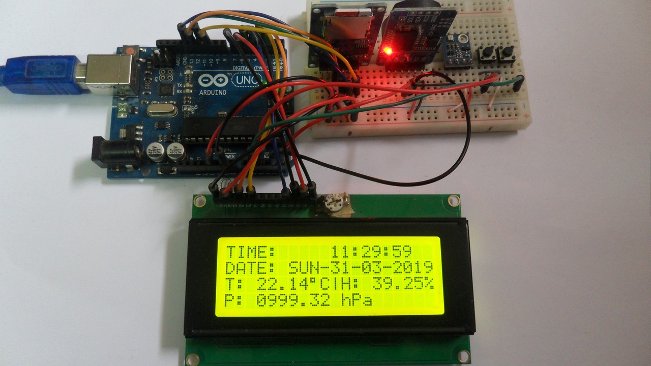
This post shows how to make an Arduino weather data logger (& station) that logs temperature (in °C), humidity (in %RH) and pressure (in hectopascal) using SD card, BME280 barometric pressure & humidity & temperature sensor.
The logged data is saved to a text file stored on the SD card. DS3231 real time clock board is used to get time and date information.
Time, date, temperature, humidity and pressure values are displayed on 20×4 LCD screen and sent to PC serial monitor.
To see how to interface Arduino with SD card, visit the following post:
Arduino and SD card example – Read and write files
To see how to interface Arduino with BME280 sensor (I2C mode) for the first time, take a look at this post:
Arduino with BME280 pressure, temperature and humidity sensor
And the link below shows how to build Arduino temperature data logger:
Arduino Temperature Data Logger with SD Card
Hardware Required:
This is a list of all components required to build this project.
- Arduino UNO board —> Board details —> Atmega328P datasheet
- micro SD card with FAT16 or FAT32 file system
- micro SD card module
- 20×4 LCD screen
- BME280 sensor module (with built-in 3.3V regulator and level shifter) —-> BME280 datasheet
- DS3231 module —-> DS3231 datasheet
- 330 ohm resistor
- 2 x push button
- 10k ohm variable resistor or potentiometer
- 3V coin cell battery
- Breadboard
- Jumper wires
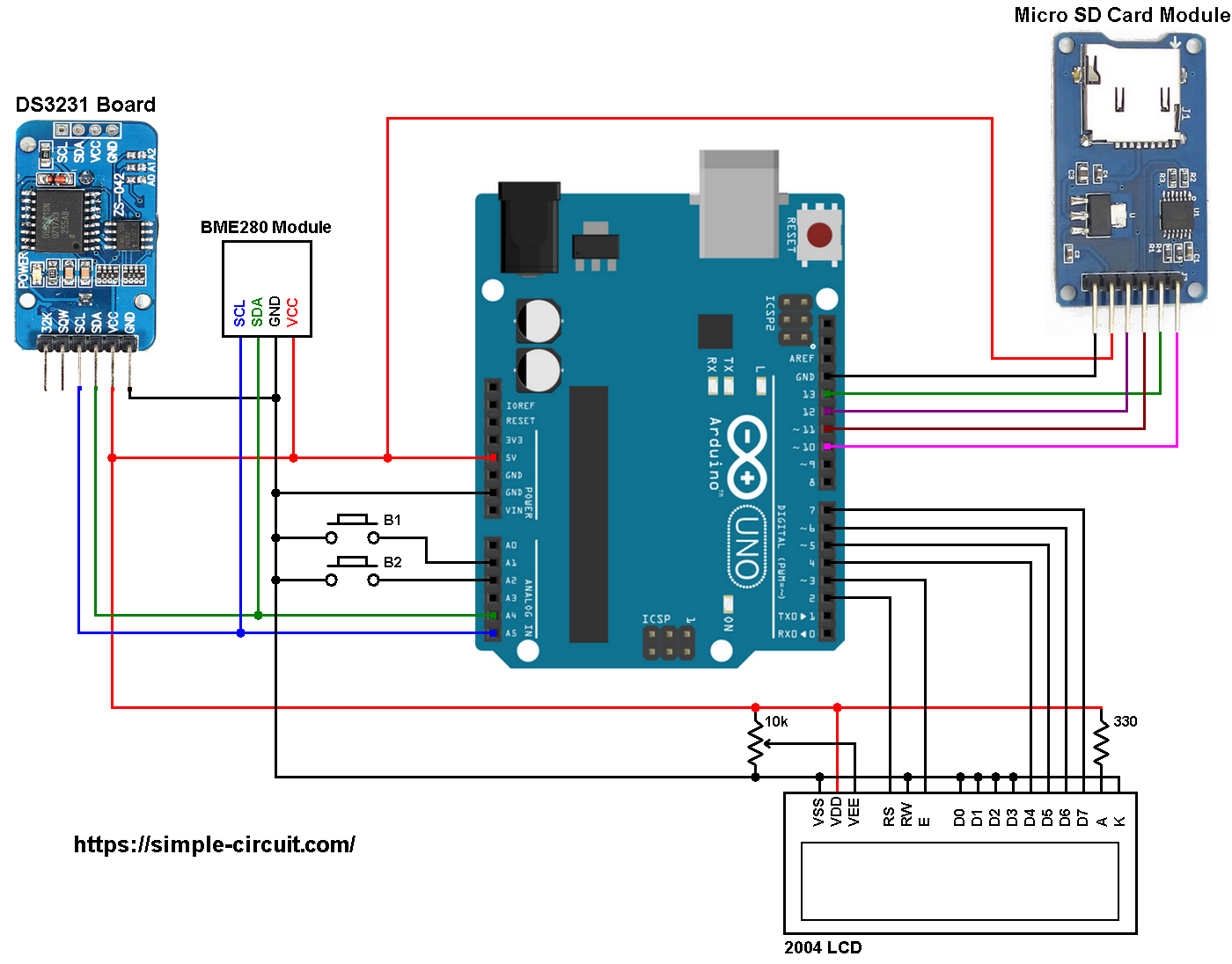
Arduino Weather Data Logger with SD Card Circuit:
The image below shows project circuit diagram.
In this project I used micro SD card module, this module is supplied from circuit 5V source that comes from the Arduino UNO board. This module contains AMS1117-3V3 voltage regulator which is used to supply the SD card with 3.3V. Also this module contains an IC which is 74LVC125A and it’s used as level translator (from 5V to 3.3V).
Hint:
The BME280 chip works with maximum voltage of 3.6V (supply voltage range is from 1.71 to 3.6V) which means we’ve to use a 3V3 voltage regulator to supply it from a 5V source.
Also, if we’re working with a 5V system (development board, microcontroller …) like the Arduino UNO board (ATmega328P microcontroller), we’ve to use a voltage level shifter (level converter) which converts the 3.3V (comes from the BME280 chip) into 5V (goes to the ATmega328P) and vice versa. This level shifter is for the I2C bus lines (clock and data).
The BME280 module shown in project circuit diagram has a built-in 3.3V regulator and level shifter.
The microSD card module is connected to the Arduino as follows (from left to right):
The first pin of the micro SD card module (GND) is connected to Arduino GND.
The second pin of the micro SD card module (VCC) is connected to Arduino 5V.
The third pin of the micro SD card module (MISO) is connected to Arduino digital pin 12.
The fourth pin of the micro SD card module (MOSI) is connected to Arduino digital pin 11.
The fifth pin of the micro SD card module (SCK) is connected to Arduino digital pin 13.
The last pin of the micro SD card module (CS) is connected to Arduino digital pin 10.
The digital pins 10, 11, 12 and 13 are hardware SPI module pins of ATmega328P microcontroller (Arduino UNO microcontroller).
The DS3231 RTC module SDA (serial data) and SCL (serial clock) pins are respectively connected to Arduino A4 and A5 pins (ATmega328P hardware I2C module pins).
VCC is connected to Arduino 5V and GND is connected to Arduino GND.
The BME280 sensor module has at least 4 pins because it can work in SPI mode or I2C mode. For the I2C mode we need 4 pins: GND, VCC, SDA and SCL where:
GND (ground) is connected to Arduino GND pin,
VCC is the supply pin which is connected to Arduino 5V pin,
SDA is I2C bus serial data line, connected to Arduino analog pin 4 (A4),
SCL is I2C bus serial clock line, connected to Arduino analog pin 5 (A5).
The DS3231 RTC and the BME280 sensor are connected to the same I2C bus (slave devices), the I2C slave address of the DS3231 chip differs from the one of the BME280 sensor, that allows the master device (Arduino) to talk to one of them (only one at a time).
The 20×4 LCD screen (4 rows and 20 columns) is used to display time, date, pressure, humidity and temperature values where:
RS —> Arduino digital pin 2
E —> Arduino digital pin 3
D4 —> Arduino digital pin 4
D5 —> Arduino digital pin 5
D6 —> Arduino digital pin 6
D7 —> Arduino digital pin 7
VSS, RW, D0, D1, D2, D3 and K are connected to Arduino GND,
VEE to the 10k ohm variable resistor (or potentiometer) output,
VDD to Arduino 5V and A to Arduino 5V through 330 ohm resistor.
VEE pin is used to control the contrast of the LCD. A (anode) and K (cathode) are the back light LED pins.
In the circuit there are two push buttons: B1 and B2, they are respectively connected to Arduino analog pins 1 (A1) and 2 (A2), these buttons are used to set time and date of the real time clock.
Arduino Weather Data Logger with SD Card Code:
The following Arduino code requires 3 libraries from Adafruit Industries:
The first library is for the DS3231 RTC, download link is below:
Adafruit RTC library —-> direct link
The 2nd one is for the BME280 sensor:
Adafruit BME280 Library —-> direct link
You may need to install the Adafruit Unified Sensor library if it’s not already installed:
Adafruit Unified Sensor library —-> direct link
After the download, go to Arduino IDE —> Sketch —> Include Library —> Add .ZIP Library … and browse for the .zip file (previously downloaded).
The same thing for the other library files.
Programming hints:
There are 4 libraries included in the Arduino code as shown below.
The first library is for the SD card,
the 2nd one is for the LCD display,
the 3rd is for the DS3231 RTC,
and the last library is for the BME280 sensor.
1 2 3 4 | #include <SD.h> // include Arduino SD library #include <LiquidCrystal.h> // include Arduino LCD library #include <RTClib.h> // include Adafruit RTC library #include <Adafruit_BME280.h> // include Adafruit BME280 sensor library |
The default I2C address of the BME280 library is defined as 0x77 and my device I2C address is 0x76.
In the code, the definition of BME280 sensor I2C slave address and the initialization of its library are as shown below:
1 2 3 4 | // define BME280 sensor I2C address: 0x76 or 0x77 (0x77 is library default address) #define BME280_I2C_ADDRESS 0x76 // initialize Adafruit BME280 library Adafruit_BME280 bme280; |
The Arduino reads pressure, temperature & humidity values from the BME280 sensor and saves them (with time and date) to the SD card every 1 second, for that I used the following if condition:
1 | if( mytime->seconds != p_second ) |
where the variable p_second is used to save only one value every 1 second.
Functions used in the code:
SD Card functions:
SD.begin(): this function initializes the SD card as well as the file system (FAT16 or FAT32), it returns 1 (true) if OK and 0 (false) if error.
SD.exists(“Log.txt”): tests whether the file “Log.txt” exists on the SD card, returns 1 if the file already exists and 0 if not.
SD.open(“Log.txt”, FILE_WRITE): opens the file “Log.txt” and moves the cursor to the end of the file. This function will create the file if it doesn’t already exist. Returns 0 if error.
dataLog.close(): closes the file associated with dataLog.
DS3231 Functions:
bool debounce (): this function is for button B1 debounce, returns 1 if button is debounced.
void RTC_display(): displays day of the week, date and time on the display.
byte edit(byte parameter): this function is for setting the real time clock, returns the edited parameter.
BME280 Functions:
bme280.begin(BME280_I2C_ADDRESS): this function initializes the BME280 sensor, returns 1 if OK and 0 if error.
Reading the values of temperature, humidity and pressure is done as shown below:
1 2 3 4 | // read temperature, humidity and pressure from the BME280 sensor float temp = bme280.readTemperature(); // get temperature in degree Celsius float humi = bme280.readHumidity(); // get humidity in rH% float pres = bme280.readPressure(); // get pressure in Pa |
Temperature, humidity and pressure values (with time and date) are displayed on the 20×4 LCD screen.
If there is a problem with the BME280 sensor (for example wrong device address) the LCD will display BME Sensor Error! on the 4th row.
Also and instead of the 3 quantities (temperature, humidity and pressure), the Arduino will print Error in the text file “Log.txt”.
1 bar = 10000 Pa = 100 hPa. ( 1 hPa = 100 Pa = 1 millibar)
Pa: Pascal
hPa: hectoPascal
Full Arduino code:
1 2 3 4 5 6 7 8 9 10 11 12 13 14 15 16 17 18 19 20 21 22 23 24 25 26 27 28 29 30 31 32 33 34 35 36 37 38 39 40 41 42 43 44 45 46 47 48 49 50 51 52 53 54 55 56 57 58 59 60 61 62 63 64 65 66 67 68 69 70 71 72 73 74 75 76 77 78 79 80 81 82 83 84 85 86 87 88 89 90 91 92 93 94 95 96 97 98 99 100 101 102 103 104 105 106 107 108 109 110 111 112 113 114 115 116 117 118 119 120 121 122 123 124 125 126 127 128 129 130 131 132 133 134 135 136 137 138 139 140 141 142 143 144 145 146 147 148 149 150 151 152 153 154 155 156 157 158 159 160 161 162 163 164 165 166 167 168 169 170 171 172 173 174 175 176 177 178 179 180 181 182 183 184 185 186 187 188 189 190 191 192 193 194 195 196 197 198 199 200 201 202 203 204 205 206 207 208 209 210 211 212 213 214 215 216 217 218 219 220 221 222 223 224 225 226 227 228 229 230 231 232 233 234 235 236 237 238 239 240 241 242 243 244 245 246 247 248 249 250 251 252 253 254 255 256 257 258 259 260 261 262 263 264 265 266 267 268 | /* Temperature, humidity & pressure data logger using Arduino UNO, SD card, BME280 sensor and DS3231 RTC. * Time, date, temperature, humidity and pressure values are displayed on 20x4 LCD. * This is a free software with NO WARRANTY. * https://simple-circuit.com/ */ #include <SD.h> // include Arduino SD library #include <LiquidCrystal.h> // include Arduino LCD library #include <RTClib.h> // include Adafruit RTC library #include <Adafruit_BME280.h> // include Adafruit BME280 sensor library // LCD module connections (RS, E, D4, D5, D6, D7) LiquidCrystal lcd(2, 3, 4, 5, 6, 7); // initialize RTC library RTC_DS3231 rtc; DateTime now; // buttons definition #define button1 A1 // button B1 is connected to Arduino pin A1 #define button2 A2 // button B2 is connected to Arduino pin A2 // define BME280 sensor I2C address: 0x76 or 0x77 (0x77 is library default address) #define BME280_I2C_ADDRESS 0x76 // initialize Adafruit BME280 library Adafruit_BME280 bme280; boolean sd_ok = 0, sensor_ok = 0; void setup() { pinMode(button1, INPUT_PULLUP); pinMode(button2, INPUT_PULLUP); rtc.begin(); // initialize RTC chip lcd.begin(20, 4); // initialize LCD module lcd.setCursor(0, 0); lcd.print("TIME:"); lcd.setCursor(0, 1); lcd.print("DATE:"); // open serial communications and wait for port to open: Serial.begin(9600); Serial.print("Initializing SD card..."); // initialize the SD card if ( !SD.begin() ) Serial.println("failed!"); // initialization error else { // initialization OK sd_ok = true; Serial.println("OK."); if( SD.exists("Log.txt") == 0 ) // test if file with name 'Log.txt' already exists { // create a text file named 'Log.txt' Serial.print("\r\nCreate 'Log.txt' file..."); File dataLog; dataLog = SD.open("Log.txt", FILE_WRITE); // create (&open) file Log.txt if(dataLog) { // if the file opened okay, write to it: Serial.println("OK"); // write some texts to 'Log.txt' file dataLog.println(" DATE | TIME | TEMPERATURE | HUMIDITY | PRESSURE"); dataLog.close(); // close the file } else Serial.println("failed!"); } } // initialize the BME280 sensor Serial.print("\r\nInitializing BME280 sensor..."); if( bme280.begin(BME280_I2C_ADDRESS) ) { Serial.println("done."); lcd.setCursor(0, 2); lcd.print("T:"); lcd.setCursor(10, 2); lcd.print("|H:"); lcd.setCursor(0, 3); lcd.print("P:"); lcd.setCursor(8, 2); lcd.write(223); // print degree symbol (°) lcd.write('C'); sensor_ok = true; } else { // connection error or device address wrong! Serial.println("failed!"); lcd.setCursor(0, 3); lcd.print("BME280 Sensor Error!"); } Serial.println("\r\n DATE | TIME | TEMPERATURE | HUMIDITY | PRESSURE"); } // main loop void loop() { now = rtc.now(); // read current time and date from the RTC chip RTC_display(); // diaplay time & calendar if( !digitalRead(button1) ) // if B1 is pressed if( debounce() ) // call debounce function (make sure B1 is pressed) { while( debounce() ); // call debounce function (wait for B1 to be released) byte hour = edit( now.hour() ); // edit hours byte minute = edit( now.minute() ); // edit minutes byte day = edit( now.day() ); // edit date byte month = edit( now.month() ); // edit month byte year = edit( now.year() - 2000 ); // edit year // write time & date data to the RTC chip rtc.adjust(DateTime(2000 + year, month, day, hour, minute, 0)); while(debounce()); // call debounce function (wait for button B1 to be released) } static byte p_second; if( p_second != now.second() ) { // read & print sensor data every 1 second char temp_a[7], humi_a[7], pres_a[12]; char buffer1[22]; p_second = now.second(); if( sensor_ok ) { // read temperature, humidity and pressure from the BME280 sensor float temp = bme280.readTemperature(); // get temperature in °C float humi = bme280.readHumidity(); // get humidity in rH% float pres = bme280.readPressure(); // get pressure in Pa // save all data to arrays // 1: temperature if(temp < 0) // if temperature is negative sprintf( temp_a, "-%02u.%02u", (int)abs(temp), (int)(abs(temp) * 100) % 100 ); else sprintf( temp_a, " %02u.%02u", (int)temp, (int)(temp * 100) % 100 ); // 2: humidity sprintf( humi_a, "%02u.%02u%%", (int)humi, (int)(humi * 100) % 100 ); // 3: pressure sprintf( pres_a, "%04u.%02u hPa", (int)(pres/100), (int)((uint32_t)pres % 100) ); // print sensor data on the LCD lcd.setCursor(2, 2); lcd.print(temp_a); // print temperature lcd.setCursor(14, 2); lcd.print(humi_a); // print humidity lcd.setCursor(3, 3); lcd.print(pres_a); // print pressure } sprintf( buffer1, "%02u-%02u-%04u | %02u:%02u:%02u", now.day(), now.month(), now.year(), now.hour(), now.minute(), now.second() ); Serial.print(buffer1); Serial.print(" | "); if(sensor_ok) { Serial.print(temp_a); Serial.print("°C | "); Serial.print(humi_a); Serial.print(" | "); Serial.println(pres_a); } else Serial.println(" Error | Error | Error"); // write data to SD card if(sd_ok) { // if the SD card was successfully initialized // open Log.txt file with write permission File dataLog; dataLog = SD.open("Log.txt", FILE_WRITE); dataLog.print(buffer1); dataLog.print(" | "); if(sensor_ok) { dataLog.print(temp_a); dataLog.print("°C | "); dataLog.print(humi_a); dataLog.print(" | "); dataLog.println(pres_a); } else dataLog.println(" Error | Error | Error"); dataLog.close(); // close the file } } delay(100); // wait 100ms } //////////////////////////////////////// RTC functions //////////////////////////////////////// void RTC_display() { char _buffer[12]; char dow_matrix[7][4] = {"SUN", "MON", "TUE", "WED", "THU", "FRI", "SAT"}; lcd.setCursor(6, 1); lcd.print( dow_matrix[now.dayOfTheWeek()] ); // print time sprintf( _buffer, "%02u:%02u:%02u", now.hour(), now.minute(), now.second() ); lcd.setCursor(10, 0); lcd.print(_buffer); // print date sprintf( _buffer, "-%02u-%02u-%04u", now.day(), now.month(), now.year() ); lcd.setCursor(9, 1); lcd.print(_buffer); } byte edit(byte parameter) { static byte i = 0, y_pos, x_pos[5] = {10, 13, 10, 13, 18}; char text[3]; sprintf(text,"%02u", parameter); if(i < 2) y_pos = 0; else y_pos = 1; while( debounce() ); // call debounce function (wait for B1 to be released) while(true) { while( !digitalRead(button2) ) { // while B2 is pressed parameter++; if(i == 0 && parameter > 23) // if hours > 23 ==> hours = 0 parameter = 0; if(i == 1 && parameter > 59) // if minutes > 59 ==> minutes = 0 parameter = 0; if(i == 2 && parameter > 31) // if day > 31 ==> day = 1 parameter = 1; if(i == 3 && parameter > 12) // If month > 12 ==> month = 1 parameter = 1; if(i == 4 && parameter > 99) // If year > 99 ==> year = 0 parameter = 0; sprintf(text,"%02u", parameter); lcd.setCursor(x_pos[i], y_pos); lcd.print(text); delay(200); // wait 200ms } lcd.setCursor(x_pos[i], y_pos); lcd.print(" "); unsigned long previous_m = millis(); while( (millis() - previous_m < 250) && digitalRead(button1) && digitalRead(button2) ) ; lcd.setCursor(x_pos[i], y_pos); lcd.print(text); previous_m = millis(); while( (millis() - previous_m < 250) && digitalRead(button1) && digitalRead(button2) ) ; if(!digitalRead(button1)) { // if button B1 is pressed i = (i + 1) % 5; // increment 'i' for the next parameter return parameter; // return parameter value and exit } } } // a small function for button1 (B1) debounce bool debounce () { byte count = 0; for(byte i = 0; i < 5; i++) { if ( !digitalRead(button1) ) count++; delay(10); } if(count > 2) return 1; else return 0; } ////////////////////////////////////// end RTC functions ////////////////////////////////////// // end of code. |
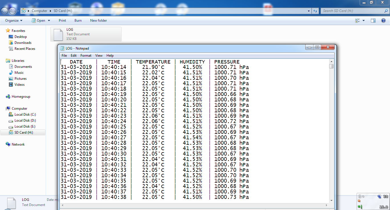
This project was tested in real hardware circuit using original Samsung microSD card with capacity of 32GB. The following image shows data logger file (Log.txt) created by the hardware circuit:
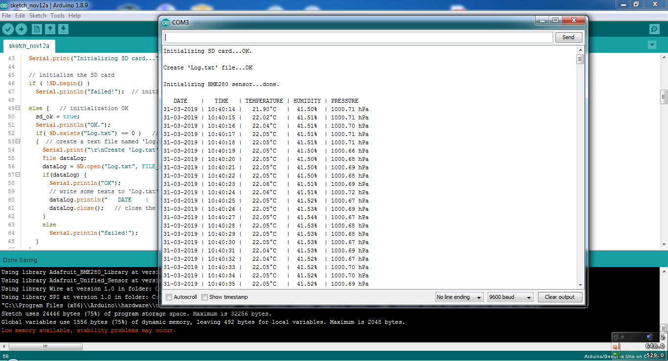
And the following one shows serial monitor output:
Discover more from Simple Circuit
Subscribe to get the latest posts sent to your email.


Hi Tanjapm,
Thank you for this interesting and informative project. It works like a dream.
I do have one question: How do I change the software to only write the data to the SD Card once a third button is pressed? The button is wired to A3. I don’t need the data to be written to the SD card unnecessarily.
hi good evening.could you please explain briefly for the code starting in line114.i want to make it record data daily
Hi dear friend,
I don`t know your name but I think it´s not so important. I have built your projekt “Arduino Weather Data Logger with SD Card” and it runs well. I´m a newbie in programming micros and I would like to realise two modifikations in this.
I would like to change the logtime from one second for example to 10 minutes and further use the LCD via I2C connection to the micro. Please be so kind and give me some help or hints to modify your sketh in order to let run these two changes.in your projekt
Best regards
Johannes Sock
written from Germany on July 16th 2020
Hi Johannes,
I assume you might have found out by now, but for anyone else stumbling upon this:
you can adapt the code starting in line 114 (in reference to the above posted ‘full Arduino Code’.
void loop()
{ p_second = rtc.now().second();
if( p_second == rtc.now().second() )
{ // all your code here
p_second = p_second+delta_t;
if(p_second >59){p_second = p_second-60;
}
you set the variable to the current second, since this condition is fulfilled you enter the if-loop and print the data, before you exit , you set the variable to the current second plus a delay of your choice. For example 10 seconds. That means the next iteration waits until delta_t has passed. If you prefer working in minutes, set your variables p_second to rtc.now().minute(). To be consistent I would rename the variable as well…
hope that helps.
Hi tanjapm,
cause I`m momentary hanndycaped I´ll try your proposal in a few weeks.
On there I´ll report into this community wether it runs or any other result.
best regards
johannes
I am loking for Full Arduino code for this problem. I have the same question.
Dear TanjapM
I enjoy using the Arduino sketch to measure temperature and humidity. I also have a problem with the short time of 1 second and would like to set it to 1, 5 and eg 10 minutes.
When making the changes after line 114 I get a lot of error messages that I can’t get right after many tries.
Could you do me a favor and send me the complete sketch with the changes already made?
I would be very happy with it.
JanW
Arduino Weather Data Logger with SD Card
http://simple-circuit.com/arduino-weather-data-logger-sd-card/