This tutorial shows how to interface PIC18F4550 microcontroller with BMP280 barometric pressure and temperature sensor from Bosch Sensortec.
The PIC18F4550 MCU reads temperature & pressure values from the BMP280 sensor and print them (respectively in °C and hPa) on SSD1306 OLED display (128×64 pixel).
CCS C compiler is used in this project.
In this project the SSD1306 OLED is configured to work in I2C mode, make sure that your display is configured to work in I2C mode, some displays need jumper placing or some soldering.
To see how to interface PIC18F4550 MCU with SSD1306 OLED display (I2C mode), take a look at the following project:
Interfacing PIC18F4550 with SSD1306 OLED
And to see how to interface PIC microcontroller with BMP280 sensor using CCS C compiler, visit this post:
Interfacing PIC MCU with BMP280 temperature and pressure sensor
Hardware Required:
- PIC18F4550 microcontroller —-> datasheet
- SSD1306 OLED display with 128×64 pixel resolution
- BMP280 sensor module (with built-in 3.3V regulator and level shifter) —-> BMP280 datasheet
- 5V source
- Breadboard
- Jumper wires
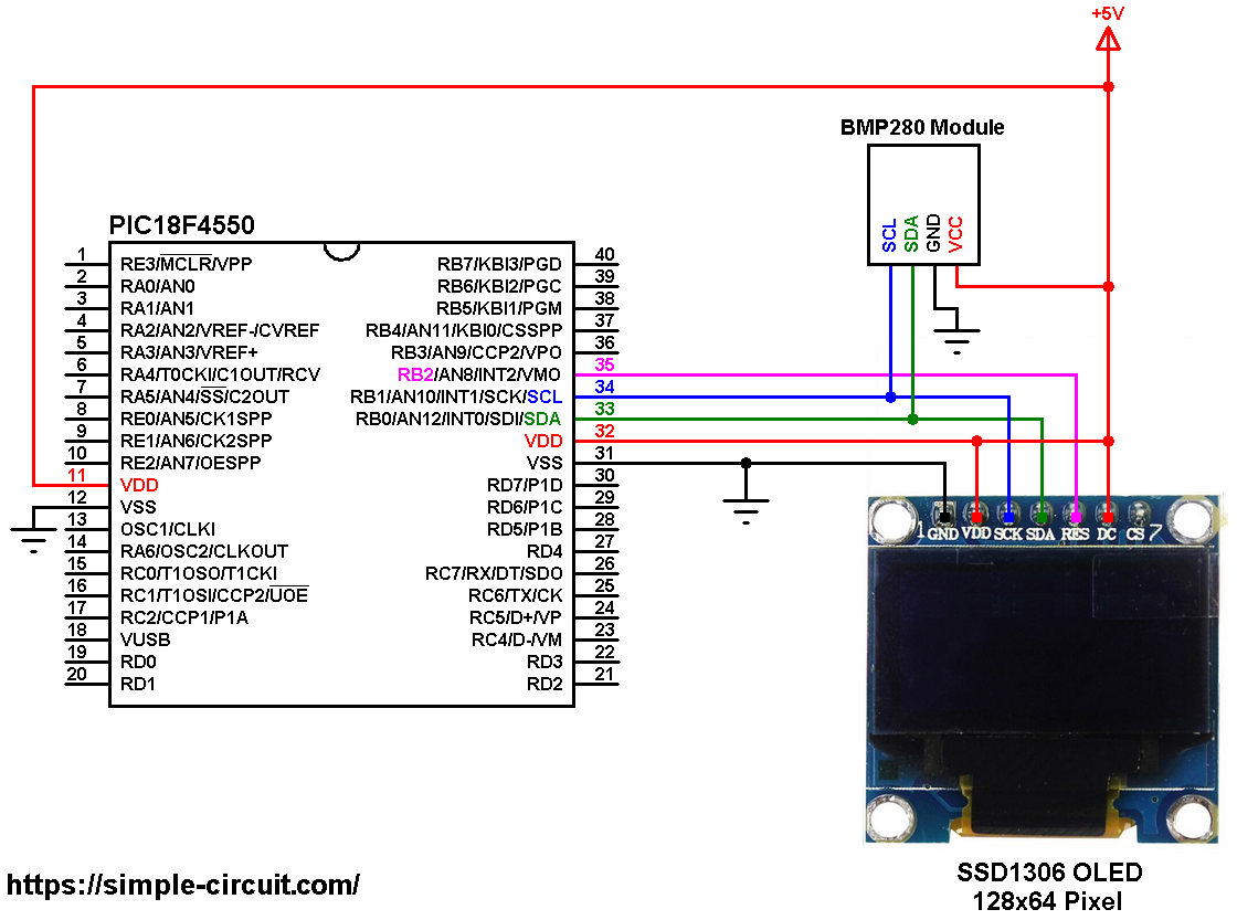
PIC18F4550 with BMP280 sensor and SSD1306 OLED circuit:
The image below shows project circuit diagram.
Hint:
The BMP280 chip works with maximum voltage of 3.6V (supply voltage range is from 1.71 to 3.6V) which means we’ve to use a 3V3 voltage regulator to supply it from a 5V source.
Also, if we’re working with a 5V system (development board, microcontroller …) like the PIC18F4550 microcontroller, we’ve to use a voltage level shifter (level converter) which converts the 3.3V (comes from the BMP280 chip) into 5V (goes to the PIC18F4550) and vice versa. This level shifter is for the I2C bus lines (clock and data).
The BMP280 module shown in project circuit diagram has a built-in 3.3V regulator and level shifter.
All the grounded terminals are connected together.
Generally, the BMP280 module has at least 4 pins because it can work in SPI mode or I2C mode. For the I2C mode we need 4 pins: VCC, GND, SDA and SCL where:
VCC is the supply pin, it is connected to +5V,
GND (ground) is connected to circuit ground (0V),
SDA is I2C bus serial data line, connected to PIC18F4550 pin RB0 (#33),
SCL is I2C bus serial clock line, connected to PIC18F4550 pin RB1 (#34).
The SSD1306 OLED display is connected to the circuit as follows:
SSD1306 OLED GND goes to circuit ground,
SSD1306 OLED VDD is connected to circuit +5V,
SSD1306 OLED SDA pin (serial data) to pin RB0 (PIC18F4550 hardware I2C SDA pin),
SSD1306 OLED SCK pin (serial clock) to pin RB1 (PIC18F4550 hardware I2C SCL pin),
SSD1306 OLED RES pin (reset) to pin RB2.
The SSD1306 OLED display DC pin is connected to VDD which means I2C slave address of the device is 0x7A. If the DC pin is connected to ground (GND) then the I2C slave address becomes 0x78.
The SSD1306 OLED and the BMP280 sensor are connected to the same I2C bus (slave devices), SCL and SDA pins of the two devices are connected to SCL (RB1) and SDA (RB0) pins of the PIC18F4550 (master device).
The I2C slave address of the SSD1306 OLED differs from the one of the BMP280 sensor, this difference allows the master device (PIC18F4550) to talk to one of them (only one at a time).
In this project the PIC18F4550 microcontroller runs with its internal oscillator @ 8 MHz, MCLR pin is configured as an input pin.
PIC18F4550 with BMP280 sensor and SSD1306 OLED C code:
The following C code is for CCS C compiler, it was tested with version 5.051.
To be able to compile the C code below with no error, a driver for the SSD1306 OLED display is required, its full name (with extension) is SSD1306OLED.c, download link is the one below:
SSD1306 OLED CCS C library download
For more information about this driver, visit the following post:
SSD1306 OLED Library for CCS C compiler
Also, another library for the BMP280 sensor is required, its full name (with extension) is BMP280_Lib.c, download link is below:
BMP280 CCS C library download
after the download of the 2 library files, add both of them to project folder or CCS C compiler drivers folder.
Programming hints:
The BMP280 I2C address and the reset pin of the SSD1306 OLED display are defined in the C code as shown below:
1 2 3 4 5 | // // SSD1306 OLED reset pin definition #define SSD1306_RST PIN_B2 // define BMP280 device I2C address: 0xEC or 0xEE (0xEE is library default address) #define BMP280_I2C_ADDRESS 0xEC |
The driver files of the SSD1306 OLED display and the BMP280 sensor are included in the code using the following 2 lines:
1 2 3 4 | // include SSD1306 OLED driver source file #include <SSD1306OLED.c> // include BMP280 sensor driver source file #include <BMP280_Lib.c> |
As any other I2C device, the BMP280 sensor has an I2C slave address which may be 0xEC or 0xEE. This address depends on the connection of the SDO pin (used for SPI mode as serial data out or MISO), if the SDO pin is connected (directly or through resistor) to VCC (3.3V) the address will be 0xEE, and if it’s connected to GND the address becomes 0xEC.
The default I2C address of the library is defined as 0xEE and my device I2C address is 0xEC.
In the code, the definition of the I2C slave address is as shown below:
1 2 | // define device I2C address: 0xEC or 0xEE (0xEE is library default address) #define BMP280_I2C_ADDRESS 0xEC |
The BMP280 sensor is initialized with the function BMP280_begin(MODE_NORMAL) which returns 1 if ok and 0 if error. In the code the initialization of the sensor is as shown below:
1 2 3 4 5 6 7 8 9 10 11 | // initialize the BMP280 sensor if(BMP280_begin(MODE_NORMAL) == 0) { // connection error or device address wrong! SSD1306_TextSize(2); // text size = 2 SSD1306_GotoXY(5, 17); SSD1306_Print("Connection"); SSD1306_GotoXY(35, 37); SSD1306_Print("Error"); SSD1306_Display(); while(TRUE); // stay here } |
Reading temperature and pressure values is done as shown below.
Note that the BMP280 library returns the temperature in hundredths °C which means we’ve to divide it by 100 and it returns the pressure in Pa, to get the pressure in hPa we’ve to divide it also by 100.
1 2 3 4 | // Read temperature (in hundredths C) and pressure (in Pa) // values from the BMP280 sensor BMP280_readTemperature(&temp); // read temperature BMP280_readPressure(&pres); // read pressure |
Temperature and pressure values are displayed on the SSD1306 OLED screen.
If there is a problem with the BMP280 sensor (for example wrong device address) the screen will display Connection Error.
1 bar = 10000 Pa = 100 hPa. ( 1 hPa = 100 Pa)
Pa: Pascal
hPa: hectoPascal
Rest of code is described through comments.
Full CCS C Code:
1 2 3 4 5 6 7 8 9 10 11 12 13 14 15 16 17 18 19 20 21 22 23 24 25 26 27 28 29 30 31 32 33 34 35 36 37 38 39 40 41 42 43 44 45 46 47 48 49 50 51 52 53 54 55 56 57 58 59 60 61 62 63 64 65 66 67 68 69 70 71 72 73 74 75 76 77 78 79 80 81 82 83 84 85 86 87 88 89 | /* * Interfacing PIC18F4550 microcontroller with SSD1306 OLED (128x64 Pixel) * and BMP280 pressure & temperature sensor. * C Code for CCS C compiler. * This is a free software with NO WARRANTY. * http://simple-circuit.com/ */ // SSD1306 OLED reset pin definition #define SSD1306_RST PIN_B2 // define BMP280 device I2C address: 0xEC or 0xEE (0xEE is library default address) #define BMP280_I2C_ADDRESS 0xEC #include <18F4550.h> #fuses NOMCLR, NOWDT, NOPROTECT, NOLVP #use delay(internal = 8MHz) #use I2C(MASTER, I2C1, FAST = 400000, stream = SSD1306_STREAM, stream = BMP280_STREAM) // include SSD1306 OLED driver source file #include <SSD1306OLED.c> // include BMP280 sensor driver source file #include <BMP280_Lib.c> // main function void main() { delay_ms(1000); // wait 1 second // initialize the SSD1306 OLED with an I2C addr = 0x7A (default address) SSD1306_Begin(SSD1306_SWITCHCAPVCC, SSD1306_I2C_ADDRESS); SSD1306_ClearDisplay(); // clear the display buffer SSD1306_SetTextWrap(false); // disable text wrap SSD1306_GotoXY(25, 0); // move cursor to position (25, 0) pixel SSD1306_Print("BMP280 SENSOR"); SSD1306_Display(); // initialize the BMP280 sensor if(BMP280_begin(MODE_NORMAL) == 0) { // connection error or device address wrong! SSD1306_TextSize(2); // text size = 2 SSD1306_GotoXY(5, 17); SSD1306_Print("Connection"); SSD1306_GotoXY(35, 37); SSD1306_Print("Error"); SSD1306_Display(); while(TRUE); // stay here } SSD1306_GotoXY(29, 11); SSD1306_Print("TEMPERATURE:"); SSD1306_GotoXY(38, 40); SSD1306_Print("PRESSURE:"); SSD1306_Display(); SSD1306_TextSize(2); // text size = 2 signed int32 temp; unsigned int32 pres; while(TRUE) { // Read temperature (in hundredths C) and pressure (in Pa) // values from the BMP280 sensor BMP280_readTemperature(&temp); // read temperature BMP280_readPressure(&pres); // read pressure // print data on the LCD // 1: print temperature SSD1306_GotoXY(11, 21); if(temp < 0) printf(SSD1306_Print, "-%02Lu.%02Lu C", abs(temp)/100, abs(temp) % 100 ); else printf(SSD1306_Print, " %02Lu.%02Lu C", temp/100, temp % 100 ); // print degree symbol ( ° ) SSD1306_DrawCircle(89, 23, 2); // draw circle // 2: print pressure SSD1306_GotoXY(3, 50); printf(SSD1306_Print, "%04Lu.%02Lu", pres/100, pres % 100 ); SSD1306_GotoXY(91, 50); SSD1306_Print("hPa"); SSD1306_Display(); // update the display delay_ms(1000); // wait a second } } // end of code. |
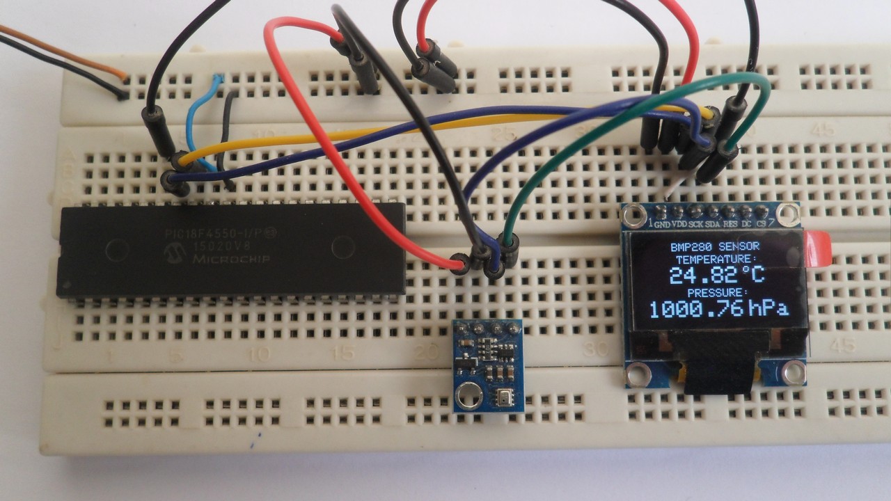
The following picture shows a protoboard circuit of the project:
Discover more from Simple Circuit
Subscribe to get the latest posts sent to your email.


