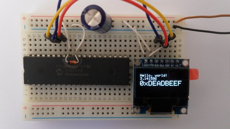
This topic shows how to interface PIC18F4550 microcontroller with SSD1306 OLED display (128×64 pixel). The SSD1306 is a monochrome display which means it has only one color (white, blue, yellow …). Also I will show how the simulation of this project (PIC18F4550 + SSD1306 OLED) with Proteus ISIS.
The SSD1306 OLED display communicates with the master device over I2C mode, SPI mode or 8-bit parallel mode. In this project I’m going to use the I2C mode.
In the I2C mode there are two lines between the microcontroller and the SSD1306 OLED display board: SDA (serial data) and SCL (serial clock). An additional pin for hardware reset is required if the display has a reset pin.
So, make sure that your SSD1306 OLED display is configured to work in I2C mode, some displays need jumper placing or soldering.
Hardware Required:
- PIC18F4550 microcontroller
- SSD1306 OLED display
- 5V source
- Breadboard
- Jumper wires
Interfacing PIC18F4550 with SSD1306 OLED display circuit:
Circuit diagram is shown below.
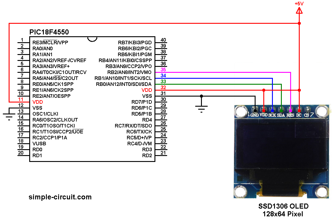
(All grounded terminal are connected together)
The PIC18F4550 microcontroller has one hardware I2C module with SDA on pin RB0 (#33) and SCL on pin RB1 (#34). The SDA pin of the MCU is connected to the SDA pin of the display and the SCL pin of the MCU is connected to the SCL pin of the display.
The reset pin of the display is connected to pin RB2 (#35) of the microcontroller.
The SSD1306 OLED display DC pin is connected to VDD which means the I2C slave address of the display is 0x7A.
In this project the PIC18F4550 runs with its internal oscillator and MCLR pin function is disabled.
The Code:
The C code below is for CCS C compiler, it was tested with version 5.051.
To be able to compile the C code below with no error, a driver for the SSD1306 OLED display is required, it’s name is SSD1306OLED.C, for more information about this driver, visit the following post:
SSD1306 OLED Library for CCS C compiler
It can be downloaded also from the link below:
SSD1306 OLED Library download
after the download, add the driver file to project folder or CCS C compiler drivers folder.
The example code is a modified version of an Adafruit example for a 128×64 pixel display.
CCS C code:
1 2 3 4 5 6 7 8 9 10 11 12 13 14 15 16 17 18 19 20 21 22 23 24 25 26 27 28 29 30 31 32 33 34 35 36 37 38 39 40 41 42 43 44 45 46 47 48 49 50 51 52 53 54 55 56 57 58 59 60 61 62 63 64 65 66 67 68 69 70 71 72 73 74 75 76 77 78 79 80 81 82 83 84 85 86 87 88 89 90 91 92 93 94 95 96 97 98 99 100 101 102 103 104 105 106 107 108 109 110 111 112 113 114 115 116 117 118 119 120 121 122 123 124 125 126 127 128 129 130 131 132 133 134 135 136 137 138 139 140 141 142 143 144 145 146 147 148 149 150 151 152 153 154 155 156 157 158 159 160 161 162 163 164 165 166 167 168 169 170 171 172 173 174 175 176 177 178 179 180 181 182 183 184 185 186 187 188 189 190 191 192 193 194 195 196 197 198 199 200 201 202 203 204 205 206 207 208 209 210 211 212 213 214 215 216 217 218 219 220 221 222 223 224 225 226 227 228 229 230 231 232 233 234 235 236 237 238 239 240 241 242 243 244 245 246 247 248 249 250 251 252 253 254 255 256 257 258 259 260 261 262 263 264 265 266 267 268 269 270 271 272 273 274 275 276 277 278 279 280 281 282 283 284 285 286 287 288 289 290 291 292 | /**************************************************************************** Interfacing PIC18F4550 microcontroller with SSD1306 OLED (128x64 Pixel) C Code for CCS C compiler Internal oscillator used @ 8MHz http://simple-circuit.com/ ***************************************************************************** This is an example for our Monochrome OLEDs based on SSD1306 drivers Pick one up today in the adafruit shop! ------> http://www.adafruit.com/category/63_98 This example is for a 128x64 size display using I2C to communicate 3 pins are required to interface (2 I2C and one reset) Adafruit invests time and resources providing this open source code, please support Adafruit and open-source hardware by purchasing products from Adafruit! Written by Limor Fried/Ladyada for Adafruit Industries. BSD license, check license.txt for more information All text above, and the splash screen must be included in any redistribution *****************************************************************************/ // SSD1306 OLED reset pin definition #define SSD1306_RST PIN_B2 #include <18F4550.h> #device PASS_STRINGS = IN_RAM #fuses NOMCLR, INTRC_IO, NOWDT, NOPROTECT, NOLVP #use delay(clock = 8MHz) #use fast_io(B) #use I2C(MASTER, I2C1, FAST = 400000, stream = SSD1306_STREAM) // Initialize I2C // Include SSD1306 OLED driver source code #include <SSD1306OLED.c> void testdrawcircle(void) { for (int8 i = 0; i < SSD1306_LCDHEIGHT; i += 2) { SSD1306_DrawCircle(SSD1306_LCDWIDTH/2, SSD1306_LCDHEIGHT/2, i); SSD1306_Display(); delay_ms(1); } } void testfillrect(void) { int1 color = TRUE; for (int8 i = 0; i < SSD1306_LCDHEIGHT/2; i += 3) { // alternate colors SSD1306_FillRect(i, i, SSD1306_LCDWIDTH - i*2, SSD1306_LCDHEIGHT - i*2, color); SSD1306_Display(); delay_ms(1); if(color) color = FALSE; else color = TRUE; } } void testdrawtriangle(void) { for (int8 i = 0; i < SSD1306_LCDHEIGHT/2; i += 5) { SSD1306_DrawTriangle(SSD1306_LCDWIDTH/2, SSD1306_LCDHEIGHT/2 - i, SSD1306_LCDWIDTH/2 - i, SSD1306_LCDHEIGHT/2 + i, SSD1306_LCDWIDTH/2 + i, SSD1306_LCDHEIGHT/2 + i); SSD1306_Display(); delay_ms(1); } } void testfilltriangle(void) { int1 color = TRUE; for (signed int16 i = SSD1306_LCDHEIGHT/2; i > 0; i -= 5) { SSD1306_FillTriangle(SSD1306_LCDWIDTH/2, SSD1306_LCDHEIGHT/2 - i, SSD1306_LCDWIDTH/2 - i, SSD1306_LCDHEIGHT/2 + i, SSD1306_LCDWIDTH/2 + i, SSD1306_LCDHEIGHT/2 + i, color); if(color) color = FALSE; else color = TRUE; SSD1306_Display(); delay_ms(1); } } void testdrawroundrect(void) { for (int8 i = 0; i < SSD1306_LCDHEIGHT/2 - 2; i += 2) { SSD1306_DrawRoundRect(i, i, SSD1306_LCDWIDTH - 2*i, SSD1306_LCDHEIGHT - 2*i, SSD1306_LCDHEIGHT/4 - i/2); SSD1306_Display(); delay_ms(1); } } void testfillroundrect(void) { int1 color = TRUE; for (int8 i = 0; i < SSD1306_LCDHEIGHT/2 - 2; i += 2) { SSD1306_FillRoundRect(i, i, SSD1306_LCDWIDTH - 2*i, SSD1306_LCDHEIGHT - 2*i, SSD1306_LCDHEIGHT/4 - i/2, color); if(color) color = FALSE; else color = TRUE; SSD1306_Display(); delay_ms(1); } } void testdrawrect(void) { for (int8 i = 0; i < SSD1306_LCDHEIGHT/2; i += 2) { SSD1306_DrawRect(i, i, SSD1306_LCDWIDTH - 2*i, SSD1306_LCDHEIGHT - 2*i); SSD1306_Display(); delay_ms(1); } } void testdrawline() { signed int16 i; for (i = 0; i < SSD1306_LCDWIDTH; i += 4) { SSD1306_DrawLine(0, 0, i, SSD1306_LCDHEIGHT - 1); SSD1306_Display(); delay_ms(1); } for (i = 0; i < SSD1306_LCDHEIGHT; i += 4) { SSD1306_DrawLine(0, 0, SSD1306_LCDWIDTH - 1, i); SSD1306_Display(); delay_ms(1); } delay_ms(250); SSD1306_ClearDisplay(); for (i = 0; i < SSD1306_LCDWIDTH; i += 4) { SSD1306_DrawLine(0, SSD1306_LCDHEIGHT - 1, i, 0); SSD1306_Display(); delay_ms(1); } for (i = SSD1306_LCDHEIGHT - 1; i >= 0; i -= 4) { SSD1306_DrawLine(0, SSD1306_LCDHEIGHT - 1, SSD1306_LCDWIDTH - 1, i); SSD1306_Display(); delay_ms(1); } delay_ms(250); SSD1306_ClearDisplay(); for (i = SSD1306_LCDWIDTH - 1; i >= 0; i -= 4) { SSD1306_DrawLine(SSD1306_LCDWIDTH - 1, SSD1306_LCDHEIGHT - 1, i, 0); SSD1306_Display(); delay_ms(1); } for (i = SSD1306_LCDHEIGHT - 1; i >= 0; i -= 4) { SSD1306_DrawLine(SSD1306_LCDWIDTH - 1, SSD1306_LCDHEIGHT - 1, 0, i); SSD1306_Display(); delay_ms(1); } delay_ms(250); SSD1306_ClearDisplay(); for (i = 0; i < SSD1306_LCDHEIGHT; i += 4) { SSD1306_DrawLine(SSD1306_LCDWIDTH - 1, 0, 0, i); SSD1306_Display(); delay_ms(1); } for (i = 0; i < SSD1306_LCDWIDTH; i += 4) { SSD1306_DrawLine(SSD1306_LCDWIDTH - 1, 0, i, SSD1306_LCDHEIGHT - 1); SSD1306_Display(); delay_ms(1); } delay_ms(250); } void testscrolltext(void) { SSD1306_ClearDisplay(); SSD1306_DrawText(58, 8, "scroll", 2); SSD1306_Display(); delay_ms(1); SSD1306_StartScrollRight(0x00, 0x0F); delay_ms(2000); SSD1306_StopScroll(); delay_ms(1000); SSD1306_StartScrollLeft(0x00, 0x0F); delay_ms(2000); SSD1306_StopScroll(); delay_ms(1000); SSD1306_StartScrollDiagRight(0x00, 0x07); delay_ms(2000); SSD1306_StartScrollDiagLeft(0x00, 0x07); delay_ms(2000); SSD1306_StopScroll(); } void main(void) { setup_oscillator(OSC_8MHZ); // Set internal oscillator to 8MHz delay_ms(1000); // Initialize the SSD1306 OLED with an I2C addr = 0x7A (default address) SSD1306_Begin(SSD1306_SWITCHCAPVCC, SSD1306_I2C_ADDRESS); // Show image buffer on the display hardware. // Since the buffer is intialized with an Adafruit splashscreen // internally, this will display the splashscreen. SSD1306_Display(); delay_ms(2000); // Clear the buffer. SSD1306_ClearDisplay(); // draw a single pixel SSD1306_DrawPixel(10, 10); // Show the display buffer on the hardware. // NOTE: You _must_ call SSD1306_Display() after making any drawing commands // to make them visible on the display hardware! SSD1306_Display(); delay_ms(2000); SSD1306_ClearDisplay(); // draw many lines testdrawline(); SSD1306_Display(); delay_ms(2000); SSD1306_ClearDisplay(); // draw rectangles testdrawrect(); SSD1306_Display(); delay_ms(2000); SSD1306_ClearDisplay(); // draw multiple rectangles testfillrect(); SSD1306_Display(); delay_ms(2000); SSD1306_ClearDisplay(); // draw mulitple circles testdrawcircle(); SSD1306_Display(); delay_ms(2000); SSD1306_ClearDisplay(); // draw a white circle, 10 pixel radius SSD1306_FillCircle(SSD1306_LCDWIDTH/2, SSD1306_LCDHEIGHT/2, 10); SSD1306_Display(); delay_ms(2000); SSD1306_ClearDisplay(); testdrawroundrect(); SSD1306_Display(); delay_ms(2000); SSD1306_ClearDisplay(); testfillroundrect(); SSD1306_Display(); delay_ms(2000); SSD1306_ClearDisplay(); testdrawtriangle(); SSD1306_Display(); delay_ms(2000); SSD1306_ClearDisplay(); testfilltriangle(); SSD1306_Display(); delay_ms(2000); SSD1306_ClearDisplay(); // draw scrolling text testscrolltext(); SSD1306_Display(); delay_ms(2000); SSD1306_ClearDisplay(); // text display tests char txt[9]; SSD1306_DrawText(2, 7, "Hello, world!", 1); sprintf(txt, "%.6f", 3.141592); SSD1306_DrawText(2, 16, txt, 1); SSD1306_DrawText(2, 26, "0x", 2); sprintf(txt, "%LX", 0xDEADBEEF); SSD1306_DrawText(26, 26, txt, 2); SSD1306_Display(); delay_ms(2000); while(TRUE) { // invert the display SSD1306_InvertDisplay(TRUE); delay_ms(1000); SSD1306_InvertDisplay(FALSE); delay_ms(1000); } } // End of code. |
The following video shows a simple hardware circuit of the project:
Proteus simulation:
This project can be simulated with Proteus simulation software, but it will not give a prefect result as the real hardware circuit. The simulation file can be downloaded from the link below, use Proteus version 8.6 or higher to open it:
PIC18F4550 + SSD1306 OLED
and the video below shows the simulation result:
Discover more from Simple Circuit
Subscribe to get the latest posts sent to your email.


Why the CSS c compiler? They have no free hobby use copies like MPLABX or MikRoC.
So when I change the pic18f4550 for the pic18f14k50, but i see the error in CCS compiler than say “no enough RAM for all variables”, what can i change for solve this error?
I bought that microcontroller and I made it work. Warning:
Some SSD1306 controllers has different address:
0x3C
0x3D
0x78
0x7A
Now, I do have a question: How can I change the presentations in order to adapt the adafruit logotype and others to my OLED 128×32?
I have to change the constants on the library, like that one?
const char Font[] = {
0x00, 0x00, 0x00, 0x00, 0x0…
Can I reduce my images so they can fit on 128×32 displays?
Hi. I noted that this driver works just fine. However, it seems that those images (like the Adafruit Logotype) only works on 128×64 displays. I have one of 128×32. How can I adapt those graphics on my display?