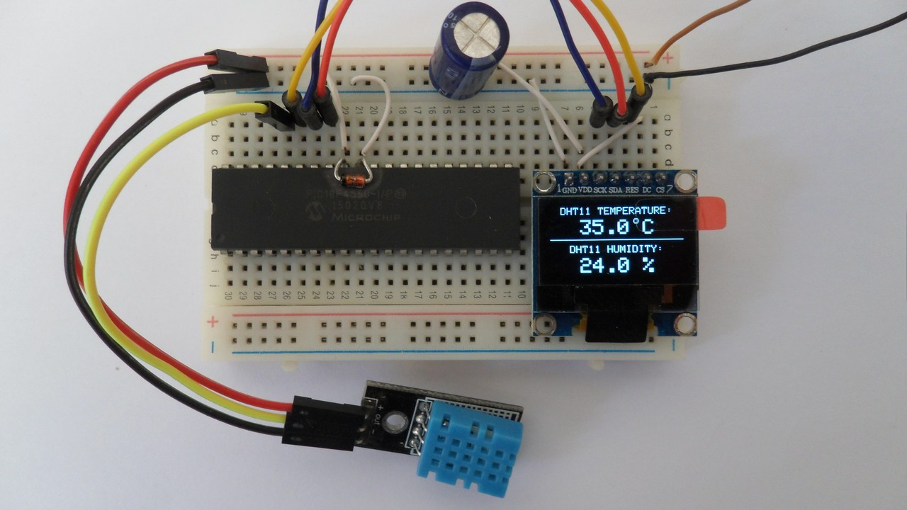
In the last PIC18F4550 project I have successfully connected this microcontroller with SSD1306 OLED display (project link is below), and now I am going to build a relative humidity and temperature measurements station using the PIC18F4550 microcontroller and DHT11 digital humidity and temperature sensor where all data are displayed on the SSD1306 display.
The SSD1306 OLED used in this post project is configured to work in I2C mode, some SSD1306 OLED boards may require a small hardware modifications (to select between SPI mode or I2C mode) such as soldering, placing jumpers …
Related Projects:
The following topics may contain some useful information about the current project.
Interfacing PIC18F4550 with SSD1306 OLED
Interfacing PIC18F4550 with DHT11 humidity and temperature sensor
Hardware Required:
- PIC18F4550 microcontroller
- SSD1306 OLED display (128×64 Pixel)
- DHT11 temperature and humidity sensor
- 4.7k ohm resistor
- 5V power source
- Breadboard
- Jumper wires
PIC18F4550 with SSD1306 OLED and DHT11 sensor circuit:
The image below shows project circuit diagram.
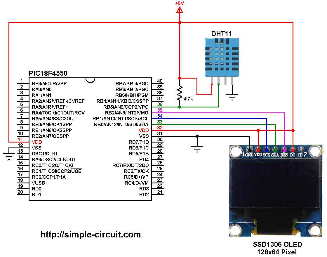
(All grounded terminal are connected together)
There are 3 wires between the PIC18F4550 microcontroller and the SSD1306 OLED display: SDA (serial data), SCL (serial clock) and reset. SDA and SCL (SCK) pins of the display are connected respectively to pin RB0 (#33) and pin RB1 (#34) of the microcontroller, these pins are hardware I2C module SDA and SCL pins.
The reset pin (RES) of the display is connected to pin RB2 (#35) of the microcontroller.
The SSD1306 OLED display DC pin is connected to VDD which means the I2C slave address of the display is 0x7A. There is no need to use this pin if your display module doesn’t have a reset pin.
The DHT11 sensor has 4 pins (from left to right): VCC (+5V), data pin, NC (not connected pin) and GND. The data pin is connected to pin RB3 (#36). A pull-up resistor of 4.7k ohm is required for the data pin.
In this project the PIC18F4550 runs with its internal oscillator and MCLR pin function is disabled.
The Code:
The C code below is for CCS C compiler, it was tested with version 5.051.
To be able to compile the C code below with no error, a driver for the SSD1306 OLED display is required, it’s name is SSD1306OLED.C, for more information about this driver, visit the following post:
SSD1306 OLED Library for CCS C compiler
It can be downloaded also from the link below:
SSD1306 OLED Library download
after the download, add the driver file to project folder or CCS C compiler drivers folder.
If there is a connection problem or checksum error the display will give “EE.E°C” and “EE.E %” instead of the temperature and humidity values as shown in the simulation video below.
Functions used in the code:
Start_Signal(): this function sends the start signal to the sensor, it sends a logic low for 25 ms and a logic high for 30 us.
Check_Response(): this function checks if there is a response from the sensor (after sending the start signal using the previous function), returns 1 (true) if ok and 0 (false) if error (for example a connection problem).
Read_Data(*dht_data): this function reads temperature and humidity data from the sensor (4 bytes), it also reads an other byte (5th byte) which is used as a checksum. This function returns 0 (false) if data read was ok and 1 (true) if there was a time out problem.
CCS C code:
1 2 3 4 5 6 7 8 9 10 11 12 13 14 15 16 17 18 19 20 21 22 23 24 25 26 27 28 29 30 31 32 33 34 35 36 37 38 39 40 41 42 43 44 45 46 47 48 49 50 51 52 53 54 55 56 57 58 59 60 61 62 63 64 65 66 67 68 69 70 71 72 73 74 75 76 77 78 79 80 81 82 83 84 85 86 87 88 89 90 91 92 93 94 95 96 97 98 99 100 101 102 103 104 105 106 107 108 109 110 111 112 113 114 115 116 117 118 119 120 121 122 123 124 125 126 127 128 129 130 131 132 133 134 135 136 137 138 139 140 141 142 143 144 145 | /****************************************************************************! PIC18F4550 microcontroller with SSD1306 OLED (128x64 Pixel) and DHT11 sensor C Code for CCS C compiler Internal oscillator used @ 8MHz http://simple-circuit.com/ *******************************************************************************/ // SSD1306 OLED reset pin definition #define SSD1306_RST PIN_B2 // DHT11 sensor connection #define DHT11_PIN PIN_B3 #include <18F4550.h> #device PASS_STRINGS = IN_RAM #fuses NOMCLR, INTRC_IO, NOWDT, NOPROTECT, NOLVP #use delay(clock = 8MHz) #use fast_io(B) #use I2C(MASTER, I2C1, FAST = 400000, stream = SSD1306_STREAM) // Initialize I2C // Include SSD1306 OLED driver source code #include <SSD1306OLED.c> char temperature[] = "00.0 C"; char humidity[] = "00.0 %"; int8 T_Byte1, T_Byte2, RH_Byte1, RH_Byte2, CheckSum; // Send start signal to the sensor void Start_Signal(void) { output_drive(DHT11_PIN); // Configure connection pin as output output_low(DHT11_PIN); // Connection pin output low delay_ms(25); // Wait 25 ms output_high(DHT11_PIN); // Connection pin output high delay_us(30); // Wait 30 us output_float(DHT11_PIN); // Configure connection pin as input } // Check sensor response int1 Check_Response(void) { set_timer1(0); // Set Timer1 value to 0 while(!input(DHT11_PIN) && get_timer1() < 100); // Wait until DHT11_PIN becomes high (cheking of 80µs low time response) if(get_timer1() >= 100) // If response time >= 100µS ==> Response error return 0; // Return 0 (Device has a problem with response) else { set_timer1(0); // Set Timer1 value to 0 while(input(DHT11_PIN) && get_timer1() < 100); // Wait until DHT11_PIN becomes low (cheking of 80µs high time response) if(get_timer1() >= 100) // If response time >= 100µS ==> Response error return 0; // Return 0 (Device has a problem with response) else return 1; // Return 1 (response OK) } } // Data read function int1 Read_Data(int8 *dht_data) { int8 j; *dht_data = 0; for(j = 0; j < 8; j++){ set_timer1(0); // Reset Timer1 while(!input(DHT11_PIN)) // Wait until DHT11_PIN becomes high if(get_timer1() >= 100) { // If low time >= 100µs ==> Time out error (Normally it takes 50µs) return 1; } set_timer1(0); // Reset Timer1 while(input(DHT11_PIN)) // Wait until DHT11_PIN becomes low if(get_timer1() > 100) { // If high time > 100µs ==> Time out error (Normally it takes 26-28µs for 0 and 70µs for 1) return 1; // Return 1 (timeout error) } if(get_timer1() > 50) // If high time > 50µS ==> Sensor sent 1 bit_set(*dht_data, (7 - j)); // Set bit (7 - j) } return 0; // Return 0 (data read OK) } // main function void main(void) { setup_oscillator(OSC_8MHZ); // Set internal oscillator to 8MHz setup_timer_1(T1_INTERNAL | T1_DIV_BY_2); // Start Timer1 with internal clock source + 2 prescaler delay_ms(1000); // Initialize the SSD1306 OLED with an I2C addr = 0x7A (default address) SSD1306_Begin(SSD1306_SWITCHCAPVCC, SSD1306_I2C_ADDRESS); // Clear the buffer SSD1306_ClearDisplay(); SSD1306_Display(); SSD1306_DrawFastHLine(0, 31, SSD1306_LCDWIDTH); SSD1306_DrawText(10, 0, "DHT11 TEMPERATURE:"); SSD1306_DrawText(19, 37, "DHT11 HUMIDITY:"); SSD1306_Display(); while(TRUE) { Start_Signal(); // Send a start signal to the sensor if(Check_Response()) { // Check if there is a response from sensor (If OK start reding humidity and temperature data) // Response OK ==> read (and save) data from the DHT11 sensor and check time out errors Read_Data(&RH_Byte1); // Read humidity 1st byte and store its value in the variable RH_Byte1 Read_Data(&RH_Byte2); // Read humidity 2nd byte and store its value in the variable RH_Byte2 Read_Data(&T_Byte1); // Read temperature 1st byte and store its value in the variable T_Byte1 Read_Data(&T_Byte2); // Read temperature 2nd byte and store its value in the variable T_Byte2 Read_Data(&CheckSum); // Read checksum and store its value in the variable CheckSum // Test if all data were sent correctly if(CheckSum == ((RH_Byte1 + RH_Byte2 + T_Byte1 + T_Byte2) & 0xFF)) { temperature[0] = T_Byte1 / 10 + 48; temperature[1] = T_Byte1 % 10 + 48; temperature[3] = T_Byte2 + 48; humidity[0] = RH_Byte1 / 10 + 48; humidity[1] = RH_Byte1 % 10 + 48; humidity[3] = RH_Byte2 + 48; } // Checksum error else { temperature[0] = temperature[1] = temperature[3] = 'E'; humidity[0] = humidity[1] = humidity[3] = 'E'; } } // Sensor response error (connection error) else { temperature[0] = temperature[1] = temperature[3] = 'E'; humidity[0] = humidity[1] = humidity[3] = 'E'; } // Display data on the display SSD1306_DrawText(29, 12, temperature, 2); // Print temperature with text size = 2 SSD1306_DrawCircle(82, 13, 2); // Put degree symbol ( ° ) SSD1306_DrawText(29, 49, humidity, 2); // Print humidity with text size = 2 SSD1306_Display(); delay_ms(1000); // Wait 1 second between readings } } // End of code. |
Finally I made a simulation of the project using Proteus software, simulation file can be downloaded from the link below, use Proteus version 8.6 or higher to open it:
PIC18F4550 + SSD1306 + DHT11
simulation result is shown in this video:
Discover more from Simple Circuit
Subscribe to get the latest posts sent to your email.


Como consigo el simulador ssd1306 para proteus?