In this blog there are some topics shows how to drive a cd-rom (dvd-rom) spindle motor using different types of PIC microcontrollers. This topic shows how to control the speed of a sensored BLDC motor using PIC16F887 microcontroller.
The BLDC motor is a three phase DC motor without brushes.
Basically there are two types of BLDC motors: sensored and sensorless. The sensored BLDC motor has 3 hall effect sensors which detect the rotor position while the sensorless BLDC motor has no hall effect sensors and it uses back emf to detect the rotor position.
The sensored BLDC motor is easy to drive because always we know the position of its rotor with the help of the hall effect sensors.
As mentioned above, the BLDC motor is a 3 phase DC motor which means it has 3 winding on the stator core. Two windings are excited at a time to create a rotating electric field. This method is fairly easy to implement, but to prevent the permanent magnet rotor from getting locked with the stator, the excitation on the stator must be sequenced in a specific manner while knowing the exact position of the rotor magnets.
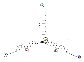
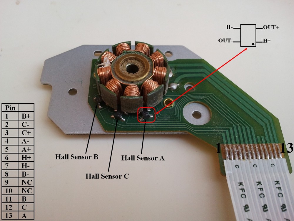
The sensored BLDC motor has 3 hall effect sensors (Sensor A, Sensor B and Sensor C) to sense rotor position, this sensors are placed as shown in the following picture. The motor which I’m going to drive has pinout as shown below (other motors may have another pinout).
In this motor each hall effect sensor has 4 pins: VCC, GND and two outputs (some sensors come with 3 pins: VCC, GND and output).
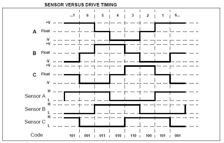
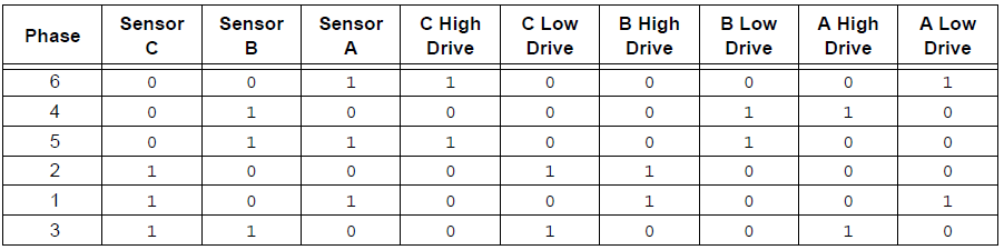
Each sensor outputs a digital high for 180 electrical degrees and outputs a digital low for the other 180 electrical degrees. The following figure shows the relationship between the sensors outputs and the required motor drive voltages for phases A, B and C.
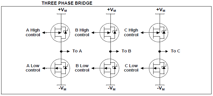
A three phase bridge is used to energize the BLDC motor windings.
According to the hall effect sensors, the 3 phase inverter bridge is controlled as shown in the following table:
Hardware Required:
- PIC16F887 microcontroller — datasheet
- 20MHz crystal oscillator
- 2 x 22pF capacitor
- Sensored BLDC motor
- 10k ohm potentiometer
- 2 x SN74LS08N — datasheet
- SN74LS04N — datasheet
- LM339 quad comparators — datasheet
- 3 x IRF4905 P-channel mosfet — datasheet
- 3 x IRF3205 N-channel mosfet — datasheet
- 3 x 2N2222A NPN transistor — datasheet
- 6 x 22K ohm resistor
- 6 x 10K ohm resistor
- 4 x 100 ohm resistor
- Protoboards
- 12V voltage source
- 5V voltage source
- Jumper wires
CD-ROM Sensored brushless DC motor drive with PIC16F887 microcontroller circuit:
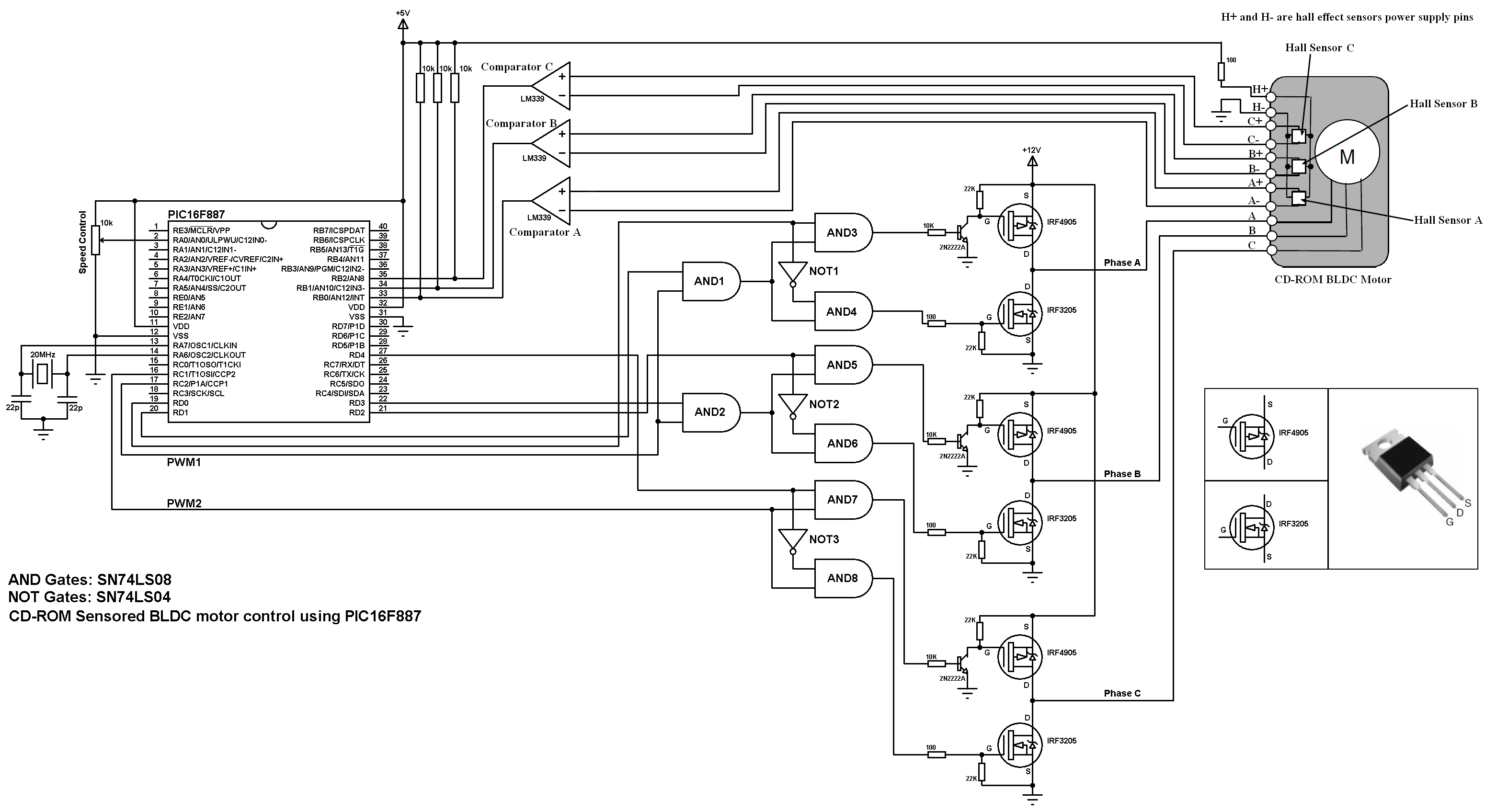
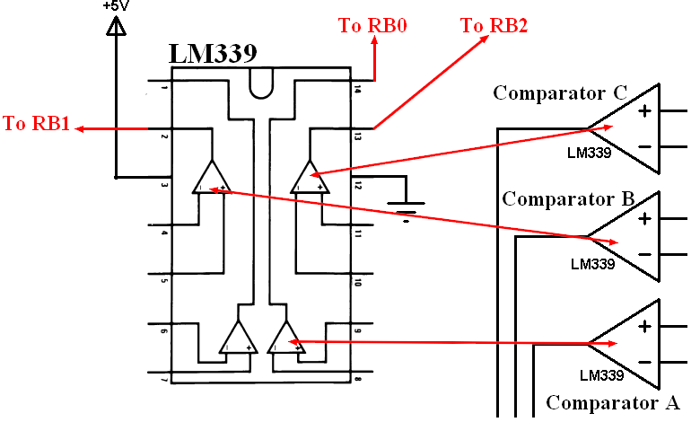
In the circuit there are 3 comparators A, B and C (LM339) which are used with the hall effect sensors to detect rotor position. The complete circuit of the LM339 is shown below:
Also in the circuit there are 8 AND and 3 NOT gates, and for that I used 2 x SN74LS08 (each one contains 4 AND gates) and one SN74LS04. The complete circuit of the three ICs is shown below:
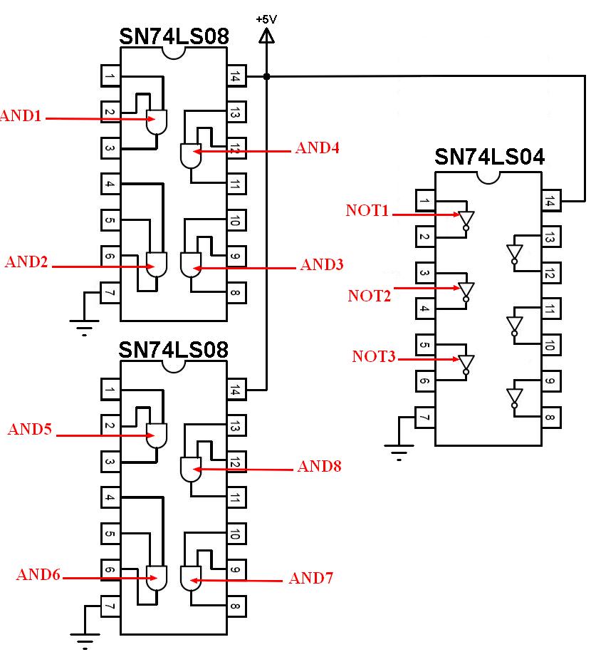
The two gates AND1 and AND2 are used to create two PWM signals from single PWM signal because PIC16F887 microcontroller has only two PWM modules and our project needs 3.
The other AND gates (AND3 – 8) and the NOT gates are used to drive the bridge mosfets and also provides a good protection to our mosfets because high and low mosfets of one line must not be ON at the same time.
A 10K ohm potentiometer is used to control the speed of the BLDC motor where its output is connected to AN0.
A 20MHZ crystal oscillator is used and MCLR pin function is disabled.
CD-ROM Sensored brushless DC motor drive with PIC16F887 microcontroller C code:
The following is code is for CCS PIC C compiler.
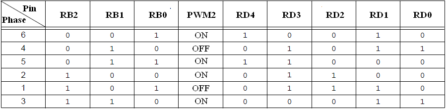
The potentiometer is used to vary the duty cycle of PWM1 and PWM2 signals which causes the speed of the BLDC motor to change. The outputs are controlled according to the following table:
The two PWM modules of the PIC16F887 are used to generate two PWM signals. Timer2 module is configured so that the each PWM signal has a frequency of 4.88KHz and 10-bit resolution:
setup_timer_2(T2_DIV_BY_4, 255, 1);
The potentiometer is used to change the duty cycle of the PWM signal which causes the speed of the BLDC motor to change.
The complete C code of this project is as the one below:
1 2 3 4 5 6 7 8 9 10 11 12 13 14 15 16 17 18 19 20 21 22 23 24 25 26 27 28 29 30 31 32 33 34 35 36 37 38 39 40 41 42 43 44 45 46 47 48 49 50 51 52 53 54 55 56 57 58 59 60 61 62 63 64 65 66 67 68 69 70 71 72 73 | /* CD-ROM sensored BLDC motor drive with PIC16F887 microcontroller CCS C code PIC16F887 runs with 20MHz crystal oscillator */ #include <16F887.h> #device ADC = 10 #fuses NOMCLR, NOBROWNOUT, NOLVP, HS #use delay(clock = 20MHz) #use fast_io(B) #use fast_io(D) int8 hall, prev_hall; int16 speed; void bldc_move(){ switch(hall){ case 1: setup_ccp2(CCP_PWM); output_d(0x12); break; case 2: setup_ccp2(CCP_OFF); output_d(0x0B); break; case 3: setup_ccp2(CCP_PWM); output_d(0x18); break; case 4: setup_ccp2(CCP_PWM); output_d(0x0C); break; case 5: setup_ccp2(CCP_OFF); output_d(0x0E); break; case 6: setup_ccp2(CCP_PWM); output_d(3); break; default: setup_ccp2(CCP_OFF); output_d(0); break; } } void main(){ output_b(0); set_tris_b(7); // Configure RB0, RB1 and RB2 as digital input pins port_b_pullups(7); // Enable internal weak pull-ups for RB0, RB1 and RB2 output_d(0); set_tris_d(0); // Configure PORTD pins as outputs setup_ccp1(CCP_PWM); // Configure CCP1 module as PWM setup_ccp2(CCP_OFF); // CCP2 module OFF setup_adc(ADC_CLOCK_INTERNAL); // ADC module uses its internal oscillator setup_adc_ports(sAN0); // Configure AN0 as analog input pin set_adc_channel(0); // Select channel AN0 setup_timer_2(T2_DIV_BY_4, 255, 1); // Set PWM frequency to 4.88KHz with a resolution of 10 bits delay_ms(1000); // Wait 1 second read_adc(ADC_START_ONLY); // ADC start only while(TRUE){ if(!adc_done()){ // If the conversion is completed speed = read_adc(ADC_READ_ONLY); // ADC read only set_pwm1_duty(speed); // Set PWM1 duty cycle set_pwm2_duty(speed); // Set PWM2 duty cycle read_adc(ADC_START_ONLY); // ADC start only } hall = input_b() & 7; // Read hall effect sensors from pins: RB0, RB1 and RB2 if(hall != prev_hall){ // If the rotor position changed bldc_move(); // Move the rotor according to hall effect senors state prev_hall = hall; // Save current rotor position } } } |
Finally the following video shows a simple hardware circuit of the project.
Discover more from Simple Circuit
Subscribe to get the latest posts sent to your email.


