This post shows how to interface the STM32 Blue Pill board with Nokia 5110 monochrome graphical LCD display module that has a resolution of 84×48 pixel.
The example shows how to print texts and draw some shapes (circles, rectangular…) on the Nokia 5110 display.
The STM32 Blue Pill development board is based on STMicroelectronics ARM Cortex-M3 microcontroller STM32F103C8T6 running at maximum clock frequency of 72MHz. This particular development board gained popularity due to its low cost and compact size, making it a popular choice for hobbyists, students, and developers.
To use the STM32 Blue Pill, a hardware programmer, such as ST-Link, is required to upload project code to the board. A USB-to-Serial converter module can also be used to upload the code to the board, an example of this converter is the popular one from FTDI which is FT232RL module.
Nokia 5110 Graphical LCD Display Module:
The Nokia 5110 LCD is a popular monochrome graphical LCD display that was originally used in the Nokia 5110 and Nokia 3110 mobile phones. It has since become a popular choice for hobbyists and developers due to its simplicity, low cost, and ease of interfacing with microcontroller based systems like Arduino, Raspberry Pi, STM32 development boards…
The Nokia 5110 display uses PCD8544 low power CMOS LCD driver with controller chip which is designed to drive graphical displays of 48 rows and 84 columns, or simply 84×48 pixels. The PCD8544 chip is responsible for managing the display’s pixels, handling communication with the microcontroller, and controlling the display’s contrast and power modes.
Specifications:
These are some specifications of the Nokia 5110 LCD.
- Display Type: Monochrome graphical Liquid Crystal Display (LCD).
- Controller: PCD8544 controller/driver.
- Resolution: 84×48 Pixels.
- Operating Voltage: Typically operates at 3.3V, including power and logic signals.
- Interface: Serial Peripheral Interface (SPI) communication protocol.
- Backlight: Built-in LED backlight that can be controlled separately.
The image below shows the Nokia 5110 LCD module used in this project:
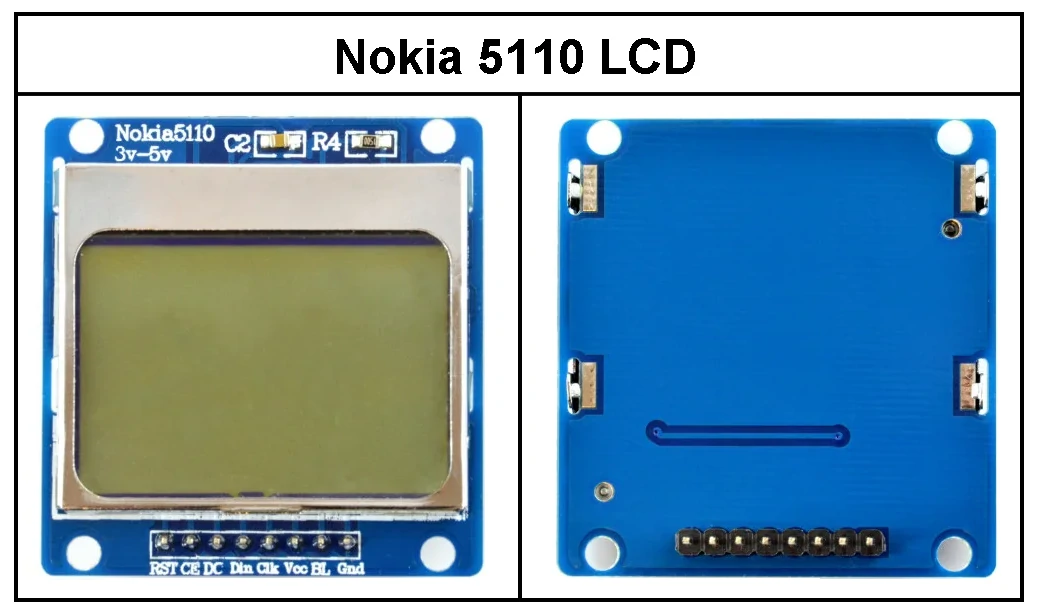
Nokia 5110 LCD Module Pinout:
The display module typically has 8 pins which are listed as below.
- GND: Ground pin, connected to circuit common ground.
- BL: Backlight LED control pin, connected to VCC, or control through PWM source.
- VCC: Power supply pin, typically 3.3V.
- CLK: Serial clock input pin for the SPI bus. Connected to the SPI clock pin (SCK) of the microcontroller.
- DIN: Serial data input pin for the SPI bus. Connected to the SPI data-out pin (MOSI) of the microcontroller.
- DC: Data/Command selection pin. Connected to a digital output pin on the microcontroller. It determines whether the data on the bus is a command or actual pixel data, with high logic level for Data and low level for Command.
- CE: Chip enable pin (active low). Connected to a digital pin on the microcontroller. Used to enable or disable the communication with the display.
- RST: Reset pin. Used to reset the display. If used, it is connected to any general purpose output pin of the microcontroller.
Interfacing STM32 Blue Pill Board with Nokia 5110 LCD:
The circuit schematic below shows the wiring diagram of the Nokia 5110 LCD display with the STM32 Blue Pill board.
In this example the display is interfaced with the microcontroller STM32F103C8T6 using bit-banging mode meaning that hardware SPI of the microcontroller is not used.
Hardware Required:
This is a summary of the parts required to build this project.
- STM32 Blue Pill board —> STM32F103C8T6 32-bit Arm Cortex-M3 MCU datasheet
- Nokia 5110 LCD module
- Bread board & Jumper wires
- STM32 Microcontroller programmer (ST-Link, USB-to-Serial converter…)
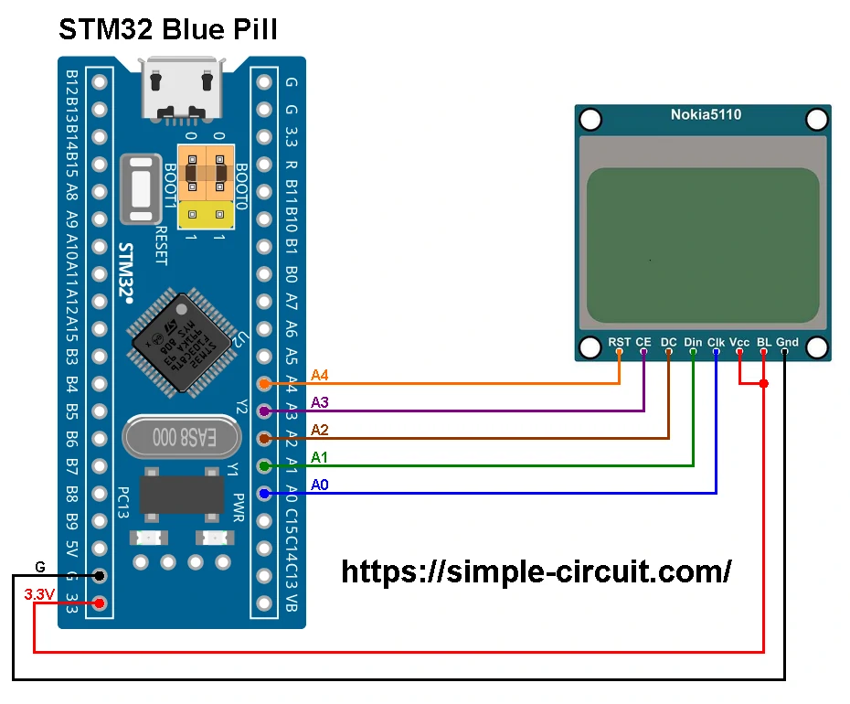
The Nokia 5110 LCD module is connected to the STM32 Blue Pill board as follows:
GND —> STM32 Blue Pill GND pin.
CLK —> STM32 Blue Pill pin PA0.
DIN —> STM32 Blue Pill pin PA1.
DC —> STM32 Blue Pill pin PA2.
CE —> STM32 Blue Pill pin PA3.
RST —> STM32 Blue Pill pin PA4.
GND Pin of the Nokia 5110 LCD module is connected to GND pin of the STM32 Blue Pill board.
BL and VCC are connected to 3.3V pin of the Blue Pill board.
Interfacing STM32 Blue Pill Board with Nokia 5110 LCD Code:
Arduino IDE (Integrated Development Environment) is used to write project code, the STM32 Blue Pill board has to be added to the IDE before compiling the code.
The STM32 Blue Pill board can be installed using Arduino IDE Boards Manager.
The FT232RL USB to serial UART converter is used to program the STM32F103C8T6 microcontroller, the ST-LINK V2 programmer also can be used and it is supported by Arduino IDE.
To be able to compile project Arduino code, two libraries are required from Adafruit Industries:
The first library is a driver for the Nokia 5110 LCD display (PCD8544 driver) and it can be installed from Arduino IDE library manager (Sketch —> Include Library —> Manage Libraries…, in the search box write “pcd8544” and install the one from Adafruit).
The second library is Adafruit graphics library which can be installed also from Arduino IDE library manager.
During installation of the Adafruit PCD8544 library, Arduino IDE may ask for installing some other libraries form Adafruit Industries (dependencies).
Project code was tested with the following library versions:
Adafruit GFX Library: Version 1.12.0.
Adafruit PCD8544 Nokia 5110 LCD Library: Version 2.0.3.
Adafruit BusIO: Version 1.17.0.
Programming Hints:
The used libraries are included in the Arduino code as shown below:
1 2 3 | #include <SPI.h> // SPI library #include <Adafruit_GFX.h> // Adafruit Graphics library #include <Adafruit_PCD8544.h> // Adafruit PCD8544 (Nokia 5110) display driver |
The connection between STM32 Blue Pill board and Nokia 5110 LCD is defined as below where bit-banging mode is used (communication is handled via software instead of hardware):
1 2 3 4 5 6 7 8 | // Nokia 5110 connection definition #define DC_PIN PA2 #define CS_PIN PA3 #define RST_PIN PA4 // Option 1: Software SPI (slower updates, more flexible pin options). #define SCLK_PIN PA0 #define MOSI_PIN PA1 Adafruit_PCD8544 display = Adafruit_PCD8544(SCLK_PIN, MOSI_PIN, DC_PIN, CS_PIN, RST_PIN); |
Note that the Arduino code for STM32 given below is originally comes as an example with the Adafruit PCD8544 library with some modification.
Full Arduino code:
1 2 3 4 5 6 7 8 9 10 11 12 13 14 15 16 17 18 19 20 21 22 23 24 25 26 27 28 29 30 31 32 33 34 35 36 37 38 39 40 41 42 43 44 45 46 47 48 49 50 51 52 53 54 55 56 57 58 59 60 61 62 63 64 65 66 67 68 69 70 71 72 73 74 75 76 77 78 79 80 81 82 83 84 85 86 87 88 89 90 91 92 93 94 95 96 97 98 99 100 101 102 103 104 105 106 107 108 109 110 111 112 113 114 115 116 117 118 119 120 121 122 123 124 125 126 127 128 129 130 131 132 133 134 135 136 137 138 139 140 141 142 143 144 145 146 147 148 149 150 151 152 153 154 155 156 157 158 159 160 161 162 163 164 165 166 167 168 169 170 171 172 173 174 175 176 177 178 179 180 181 182 183 184 185 186 187 188 189 190 191 192 193 194 195 196 197 198 199 200 201 202 203 204 205 206 207 208 209 210 211 212 213 214 215 216 217 218 219 220 221 222 223 224 225 226 227 228 229 230 231 232 233 234 235 236 237 238 239 240 241 242 243 244 245 246 247 248 249 250 251 252 253 254 255 256 257 258 259 260 261 262 263 264 265 266 267 268 269 270 271 272 273 274 275 276 277 278 279 280 281 282 283 284 285 286 287 288 289 290 291 292 293 294 295 296 297 298 299 300 301 302 303 304 305 306 307 308 309 310 311 312 313 314 315 316 317 318 319 320 321 322 323 324 325 326 327 328 329 330 331 332 333 334 335 336 337 338 339 340 341 342 343 344 345 346 347 348 349 350 351 352 353 354 355 356 357 358 359 360 361 362 363 364 365 366 367 368 369 370 371 372 373 374 375 376 377 378 379 380 381 382 383 384 385 386 387 388 | /****************************************************************************** * Interfacing STM32 Blue Pill board with Nokia 5110 graphic LCD screen. * This is a free software with NO WARRANTY. * https://simple-circuit.com/ /*******************************************************************************/ #include <SPI.h> // SPI library #include <Adafruit_GFX.h> // Adafruit Graphics library #include <Adafruit_PCD8544.h> // Adafruit PCD8544 (Nokia 5110) display driver // Nokia 5110 connection definition #define DC_PIN PA2 #define CS_PIN PA3 #define RST_PIN PA4 // Option 1: Software SPI (slower updates, more flexible pin options). #define SCLK_PIN PA0 #define MOSI_PIN PA1 Adafruit_PCD8544 display = Adafruit_PCD8544(SCLK_PIN, MOSI_PIN, DC_PIN, CS_PIN, RST_PIN); // Option 2: Hardware SPI (faster, but must use certain hardware pins). // For STM32 Blue Pill board: SCK = PA5, and MOSI = PA7 // To use hardware SPI comment the above (Option 1) and uncomment the below line. //Adafruit_PCD8544 display = Adafruit_PCD8544(DC_PIN, CS_PIN, RST_PIN); #define NUMFLAKES 10 #define XPOS 0 #define YPOS 1 #define DELTAY 2 #define LOGO16_GLCD_HEIGHT 16 #define LOGO16_GLCD_WIDTH 16 static const unsigned char PROGMEM logo16_glcd_bmp[] = { 0B00000000, 0B11000000, 0B00000001, 0B11000000, 0B00000001, 0B11000000, 0B00000011, 0B11100000, 0B11110011, 0B11100000, 0B11111110, 0B11111000, 0B01111110, 0B11111111, 0B00110011, 0B10011111, 0B00011111, 0B11111100, 0B00001101, 0B01110000, 0B00011011, 0B10100000, 0B00111111, 0B11100000, 0B00111111, 0B11110000, 0B01111100, 0B11110000, 0B01110000, 0B01110000, 0B00000000, 0B00110000 }; void setup() { Serial.begin(9600); Serial.println("PCD test"); // Initialize the display display.begin(); // init done // you can change the contrast around to adapt the display // for the best viewing! display.setContrast(55); display.display(); // show splashscreen delay(2000); display.clearDisplay(); // clears the screen and buffer // draw a single pixel display.drawPixel(10, 10, BLACK); display.display(); delay(2000); display.clearDisplay(); // draw many lines testdrawline(); display.display(); delay(2000); display.clearDisplay(); // draw rectangles testdrawrect(); display.display(); delay(2000); display.clearDisplay(); // draw multiple rectangles testfillrect(); display.display(); delay(2000); display.clearDisplay(); // draw mulitple circles testdrawcircle(); display.display(); delay(2000); display.clearDisplay(); // draw a circle, 10 pixel radius display.fillCircle(display.width()/2, display.height()/2, 10, BLACK); display.display(); delay(2000); display.clearDisplay(); testdrawroundrect(); delay(2000); display.clearDisplay(); testfillroundrect(); delay(2000); display.clearDisplay(); testdrawtriangle(); delay(2000); display.clearDisplay(); testfilltriangle(); delay(2000); display.clearDisplay(); // draw the first ~12 characters in the font testdrawchar(); display.display(); delay(2000); display.clearDisplay(); // text display tests display.setTextSize(1); display.setTextColor(BLACK); display.setCursor(0,0); display.println("Hello, world!"); display.setTextColor(WHITE, BLACK); // 'inverted' text display.println(3.141592); display.setTextSize(2); display.setTextColor(BLACK); display.print("0x"); display.println(0xDEADBEEF, HEX); display.display(); delay(2000); // rotation example display.clearDisplay(); display.setRotation(1); // rotate 90 degrees counter clockwise, can also use values of 2 and 3 to go further. display.setTextSize(1); display.setTextColor(BLACK); display.setCursor(0,0); display.println("Rotation"); display.setTextSize(2); display.println("Example!"); display.display(); delay(2000); // revert back to no rotation display.setRotation(0); // miniature bitmap display display.clearDisplay(); display.drawBitmap(30, 16, logo16_glcd_bmp, 16, 16, 1); display.display(); // invert the display display.invertDisplay(true); delay(1000); display.invertDisplay(false); delay(1000); // draw a bitmap icon and 'animate' movement testdrawbitmap(logo16_glcd_bmp, LOGO16_GLCD_WIDTH, LOGO16_GLCD_HEIGHT); } void loop() { } void testdrawbitmap(const uint8_t *bitmap, uint8_t w, uint8_t h) { uint8_t icons[NUMFLAKES][3]; randomSeed(666); // whatever seed // initialize for (uint8_t f=0; f< NUMFLAKES; f++) { icons[f][XPOS] = random(display.width()); icons[f][YPOS] = 0; icons[f][DELTAY] = random(5) + 1; Serial.print("x: "); Serial.print(icons[f][XPOS], DEC); Serial.print(" y: "); Serial.print(icons[f][YPOS], DEC); Serial.print(" dy: "); Serial.println(icons[f][DELTAY], DEC); } while (1) { // draw each icon for (uint8_t f=0; f< NUMFLAKES; f++) { display.drawBitmap(icons[f][XPOS], icons[f][YPOS], bitmap, w, h, BLACK); } display.display(); delay(200); while(Serial.available()) { switch (Serial.read()) { case 'w':display.setContrast(display.getContrast() + 1); break; case 's':if(display.getContrast()) display.setContrast(display.getContrast() - 1); break; case 'e':display.setBias(display.getBias() + 1); break; case 'd':if(display.getBias()) display.setBias(display.getBias() - 1); break; case 'R':display.setReinitInterval(10); break; case 'r':display.initDisplay(); display.setReinitInterval(0); break; } } Serial.print("contrast (w/s): 0x"); Serial.print(display.getContrast(), HEX); Serial.print(" bias (e/d): 0x"); Serial.print(display.getBias(), HEX); Serial.print(" reinitialize display (r/R): 0x"); Serial.print(display.getReinitInterval(), HEX); Serial.print(" \r"); // then erase it + move it for (uint8_t f=0; f< NUMFLAKES; f++) { display.drawBitmap(icons[f][XPOS], icons[f][YPOS], logo16_glcd_bmp, w, h, WHITE); // move it icons[f][YPOS] += icons[f][DELTAY]; // if its gone, reinit if (icons[f][YPOS] > display.height()) { icons[f][XPOS] = random(display.width()); icons[f][YPOS] = 0; icons[f][DELTAY] = random(5) + 1; } } } } void testdrawchar(void) { display.setTextSize(1); display.setTextColor(BLACK); display.setCursor(0,0); for (uint8_t i=0; i < 168; i++) { if (i == '\n') continue; display.write(i); //if ((i > 0) && (i % 14 == 0)) //display.println(); } display.display(); } void testdrawcircle(void) { for (int16_t i=0; i<display.height(); i+=2) { display.drawCircle(display.width()/2, display.height()/2, i, BLACK); display.display(); } } void testfillrect(void) { uint8_t color = 1; for (int16_t i=0; i<display.height()/2; i+=3) { // alternate colors display.fillRect(i, i, display.width()-i*2, display.height()-i*2, color%2); display.display(); color++; } } void testdrawtriangle(void) { for (int16_t i=0; i<min(display.width(),display.height())/2; i+=5) { display.drawTriangle(display.width()/2, display.height()/2-i, display.width()/2-i, display.height()/2+i, display.width()/2+i, display.height()/2+i, BLACK); display.display(); } } void testfilltriangle(void) { uint8_t color = BLACK; for (int16_t i=min(display.width(),display.height())/2; i>0; i-=5) { display.fillTriangle(display.width()/2, display.height()/2-i, display.width()/2-i, display.height()/2+i, display.width()/2+i, display.height()/2+i, color); if (color == WHITE) color = BLACK; else color = WHITE; display.display(); } } void testdrawroundrect(void) { for (int16_t i=0; i<display.height()/2-2; i+=2) { display.drawRoundRect(i, i, display.width()-2*i, display.height()-2*i, display.height()/4, BLACK); display.display(); } } void testfillroundrect(void) { uint8_t color = BLACK; for (int16_t i=0; i<display.height()/2-2; i+=2) { display.fillRoundRect(i, i, display.width()-2*i, display.height()-2*i, display.height()/4, color); if (color == WHITE) color = BLACK; else color = WHITE; display.display(); } } void testdrawrect(void) { for (int16_t i=0; i<display.height()/2; i+=2) { display.drawRect(i, i, display.width()-2*i, display.height()-2*i, BLACK); display.display(); } } void testdrawline() { for (int16_t i=0; i<display.width(); i+=4) { display.drawLine(0, 0, i, display.height()-1, BLACK); display.display(); } for (int16_t i=0; i<display.height(); i+=4) { display.drawLine(0, 0, display.width()-1, i, BLACK); display.display(); } delay(250); display.clearDisplay(); for (int16_t i=0; i<display.width(); i+=4) { display.drawLine(0, display.height()-1, i, 0, BLACK); display.display(); } for (int8_t i=display.height()-1; i>=0; i-=4) { display.drawLine(0, display.height()-1, display.width()-1, i, BLACK); display.display(); } delay(250); display.clearDisplay(); for (int16_t i=display.width()-1; i>=0; i-=4) { display.drawLine(display.width()-1, display.height()-1, i, 0, BLACK); display.display(); } for (int16_t i=display.height()-1; i>=0; i-=4) { display.drawLine(display.width()-1, display.height()-1, 0, i, BLACK); display.display(); } delay(250); display.clearDisplay(); for (int16_t i=0; i<display.height(); i+=4) { display.drawLine(display.width()-1, 0, 0, i, BLACK); display.display(); } for (int16_t i=0; i<display.width(); i+=4) { display.drawLine(display.width()-1, 0, i, display.height()-1, BLACK); display.display(); } delay(250); } // End of code. // https://simple-circuit.com/ /********************************************************************* This is an example sketch for our Monochrome Nokia 5110 LCD Displays Pick one up today in the adafruit shop! ------> http://www.adafruit.com/products/338 These displays use SPI to communicate, 4 or 5 pins are required to interface Adafruit invests time and resources providing this open source code, please support Adafruit and open-source hardware by purchasing products from Adafruit! Written by Limor Fried/Ladyada for Adafruit Industries. BSD license, check license.txt for more information All text above, and the splash screen must be included in any redistribution *********************************************************************/ |
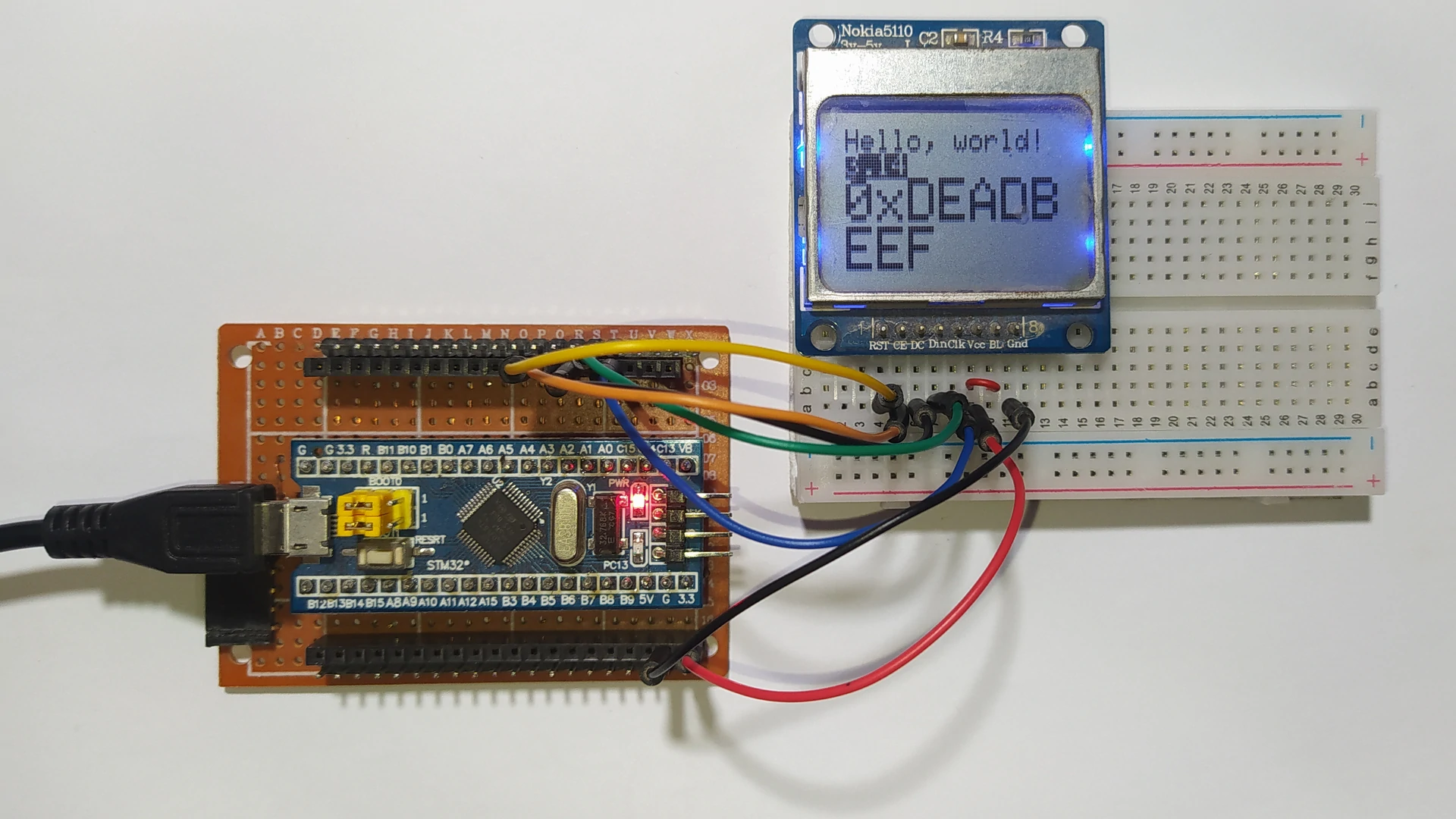
Interfacing STM32 Blue Pill Board with Nokia 5110 LCD Video:
The video below shows a hardware test circuit for the STM32 Blue Pill board and Nokia 5110 LCD.
Proteus Simulation:
The interfacing of STM32 Blue Pill board with Nokia 5110 LCD can be simulated with Proteus simulation software, the following video shows simulation results.
Proteus simulation file download link is below, use version 8.15 or higher to open it:
STM32 Blue Pill with Nokia 5110 LCD – Proteus simulation
Discover more from Simple Circuit
Subscribe to get the latest posts sent to your email.
Bonjour, câbler conformément, matériel neuf, c’est dommage mais ne fonctionne pas. KAMOD BLUE PILL et ST LINK V2.
Cordialement
hi