This post shows how to interface STMicroelectronics ARM Cortex-M3 microcontroller based STM32F103C8T6 Blue Pill development board with DHT11 digital temperature & humidity sensor where Arduino IDE software is used to write the interfacing program. We will also see the simulation of the STM32F103C8T6 Blue Pill board with the DHT11 sensor using Proteus simulation software.
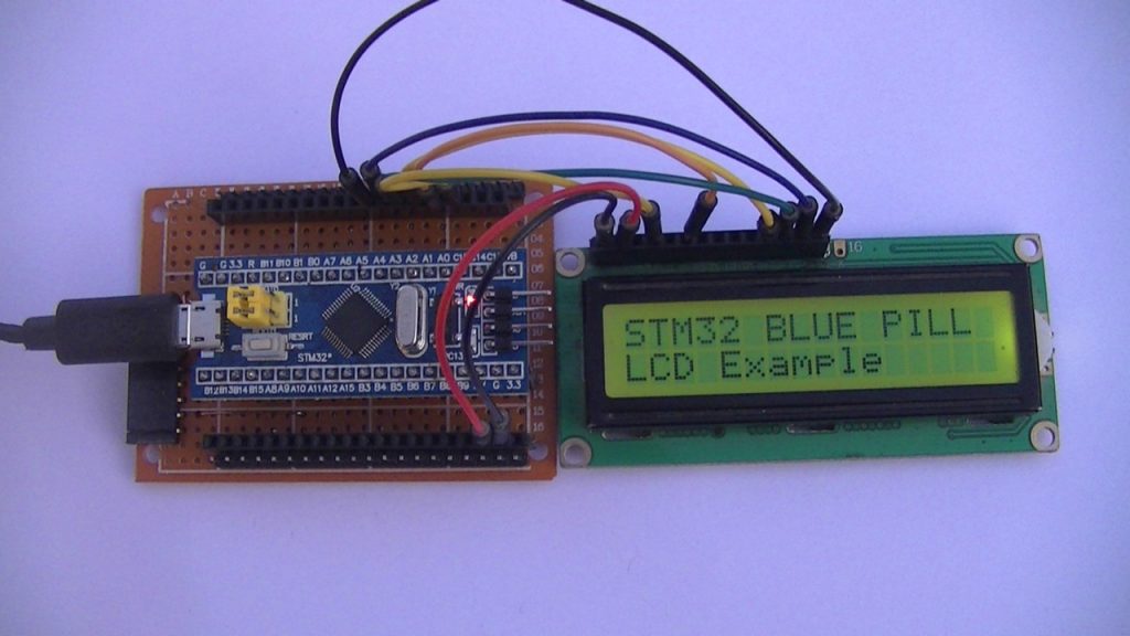
The STM32 Blue Pill board MCU reads temperature (in °C) & humidity (in rH%) values from the DHT11 sensor and print their values on 16×2 LCD display. To see how to interface STM32 Blue Pill board with 16×2 LCD go to the the following post:
Interfacing STM32 Blue Pill with 1602 LCD
About DHT11 sensor:
The DHT11 is a device used to measure temperature and relative humidity. This sensor uses a resistive-type humidity measurement component and an NTC temperature measurement component which are connected to an integrated 8-bit microcontroller.
The DHT11 sensor uses only one data pin for the communication with the microcontroller which makes the connection circuit very simple. The DHT11 sensor can work with 3.3V and 5V microcontrollers with no problem.
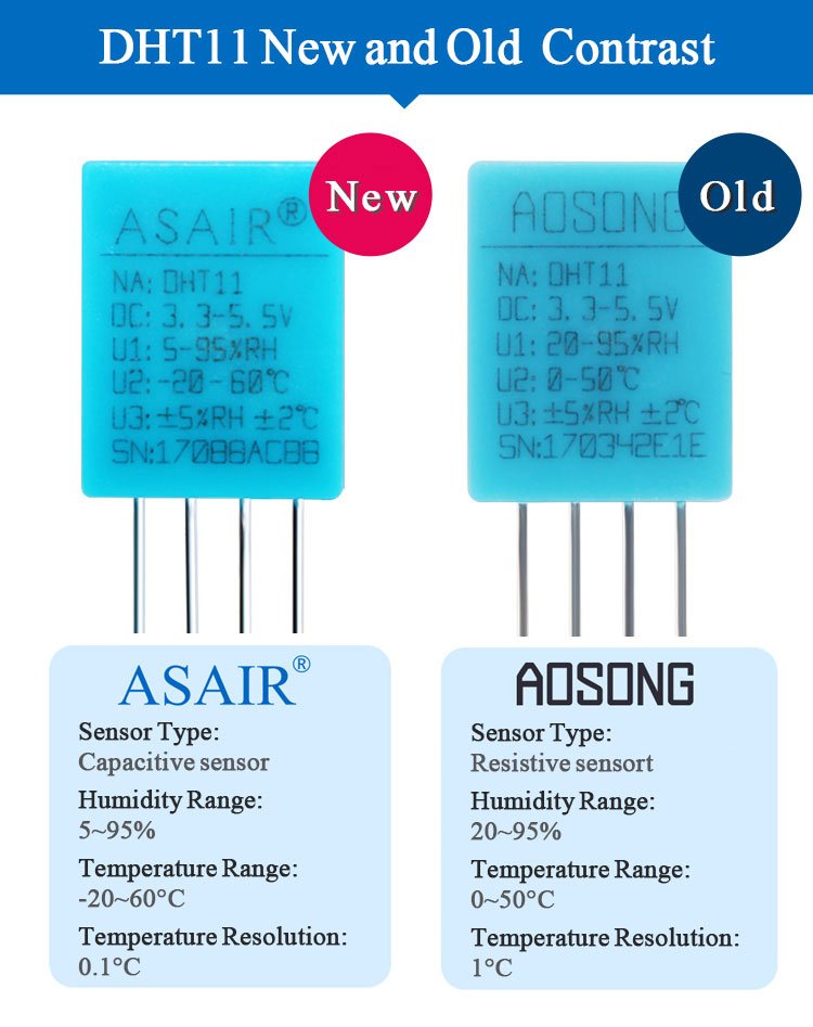
There are two types of the DHT11 sensor: old type (AOSONG) and new type (ASAIR). The differences between the 2 types are summarized below:
Interfacing DHT11 Temperature & Humidity Sensor with STM32 Blue Pill circuit:
The image below shows project circuit diagram.

Hardware required:
This is a summary of circuit required parts.
- STM32 Blue Pill board —> STM32F103C8T6 32-bit Arm Cortex-M3 MCU
- 1602 LCD screen —> HD44780 datasheet
- DHT11 (RHT01) humidity and temperature sensor —-> datasheet
- 5.1k ohm resistor (R1)
- 10k ohm variable resistor (R2)
- Breadboard & jumper wires…
- FTDI FT232RL USB-to-UART converter (for burning program file to the MCU)
Circuit description:
The DHT11 sensor has 4 pins (from left to right):
Pin 1 is power supply pin, connected to STM32 Blue Pill board 3V3 pin,
Pin 2: data pin, connected to STM32 Blue Pill board A6 pin (PA6),
Pin 3: not connected pin,
Pin 4: GND (ground), connected to STM32 Blue Pill board GND pin.
A pull-up resistor of 5.1k ohm is required because the DHT11 sensor output is open drain type.
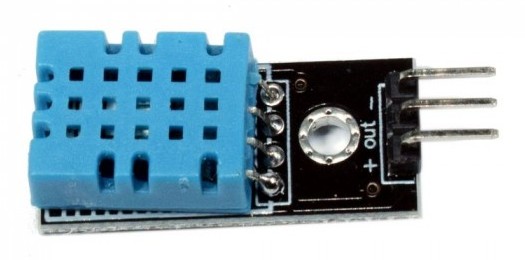
There are some DHT11 breakout modules that comes with built-in pull up resistor as the one shown below. Using a module can make the circuit more cleaner and easier.
The main power source of the circuit comes from the micro USB port of the STM32 Blue Pill board with voltage of 5V. The board contains a voltage regulator that feeds the STM32F103C8T6 microcontroller with 3.3V. The 16×2 LCD module is powered with 5V from the STM32 Blue Pill board where its ‘VDD’ pin is connected to ‘5V’ pin of the board.
Other 1602 LCD pins are connected to the STM32 Blue Pill board as follows:
RS —> pin PA0
E —> pin PA1
D4 —> pin PA2
D5 —> pin PA3
D6 —> pin PA4
D7 —> pin PA5
VSS, RW, D0, D1, D2, D3 and K are connected to circuit ground
VEE to the variable resistor (or potentiometer) output
VDD and A to +5V (from the board).
VEE pin is used to control the contrast of the LCD. A (anode) and K (cathode) are the back light LED pins.
Interfacing STM32F103C8T6 Blue Pill with DHT11 sensor Arduino code:
Arduino IDE is used to write project code, the STM32 Blue Pill board has to be added to the IDE before compilation.
The STM32 Blue Pill board can be installed using Arduino IDE Boards Manager.
The FT232RL USB to serial UART converter is used to program the STM32F103C8T6 microcontroller, the ST-LINK V2 programmer also can be used and it is supported by the Arduino IDE.
To make the Arduino code simple and easy to understood I used a library for the DHT11 sensor form Adafruit Industries. Installing the library is so easy, just go to Sketch —> Include Library —> Manage Libraries …, in the search box write “dht” and install the one from Adafruit (during installation of the library Arduino IDE may ask for installing Adafruit Unified Sensor library).
The library also can be installed manually (offline installation), first download it from the following GitHub link:
Adafruit DHT library —-> direct link
You may need to install Adafruit Unified Sensor library if it’s not already installed, download link is below:
Adafruit Unified Sensor library —-> direct link
After the download, go to Arduino IDE —> Sketch —> Include Library —> Add .ZIP Library … and browse for the .zip file (previously downloaded).
Hints:
The interfacing Arduino code uses two libraries, the first one is built-in library (comes with STM32 Blue Pill board installation) and the 2nd library is for the DHT11 sensor. The 2 libraries are included in the Arduino code as shown below:
1 2 3 4 | // include LCD library code #include <LiquidCrystal.h> // include Adafruit DHT library code #include <DHT.h> |
The connection between the STM32 Blue Pill board and the 16×2 LCD is as shown in the above circuit schematic, it is defined in the Arduino code as shown below:
1 2 | // LCD module connections (RS, E, D4, D5, D6, D7) LiquidCrystal lcd(PA0, PA1, PA2, PA3, PA4, PA5); |
The Adafruit DHT library requires some definitions such as sensor type and data pin:
1 2 3 | #define DHTPIN PA6 // DHT11 data pin is connected to Blue Pill PA6 pin #define DHTTYPE DHT11 // DHT11 sensor is used DHT dht11(DHTPIN, DHTTYPE); // initialize DHT library |
Rest of code is described through comments.
1 2 3 4 5 6 7 8 9 10 11 12 13 14 15 16 17 18 19 20 21 22 23 24 25 26 27 28 29 30 31 32 33 34 35 36 37 38 39 40 41 42 43 44 45 46 47 48 49 50 51 52 53 54 55 56 57 58 59 60 61 62 63 64 65 66 67 68 69 70 71 72 73 74 75 76 | /*************************************************************************** * * Interfacing STM32F103C8T6 Blue Pill board with DHT11 digital temperature * and humidity sensor. * Temperature and humidity values are printed on 16x2 LCD screen. * This is a free software with NO WARRANTY - Use it at your own risk! * http://simple-circuit.com/ * ***************************************************************************/ // include LCD library code #include <LiquidCrystal.h> // include Adafruit DHT library code #include <DHT.h> // LCD module connections (RS, E, D4, D5, D6, D7) LiquidCrystal lcd(PA0, PA1, PA2, PA3, PA4, PA5); #define DHTPIN PA6 // DHT11 data pin is connected to Blue Pill PA6 pin #define DHTTYPE DHT11 // DHT11 sensor is used DHT dht11(DHTPIN, DHTTYPE); // initialize DHT library void setup() { // set up the LCD's number of columns and rows lcd.begin(16, 2); lcd.setCursor(0, 0); // move cursor to position (0, 0) -- 1st column & 1st row lcd.print("STM32 Blue Pill"); // print text on the LCD lcd.setCursor(0, 1); // move cursor to position (0, 1) -- 1st column & 2nd row lcd.print("& DHT11 Sensor"); // print text on the LCD delay(5000); // wait 5 seconds lcd.clear(); // clear the display lcd.setCursor(0, 0); // move cursor to position (0, 0) -- 1st column & 1st row lcd.print("Temp:"); // print text on the LCD lcd.setCursor(0, 1); // move cursor to position (0, 1) -- 1st column & 2nd row lcd.print("Humi:"); // print text on the LCD // initialize DHT11 sensor dht11.begin(); } // data display buffer char dis_buf[7]; void loop() { delay(1000); // wait 1 second between readings // read humidity in rH% uint16_t Humi = dht11.readHumidity() * 10; // read temperature in degrees Celsius uint16_t Temp = dht11.readTemperature() * 10; // Check if any reads failed and exit early (to try again) if (isnan(Humi) || isnan(Temp)) { lcd.clear(); lcd.setCursor(5, 0); lcd.print("Error"); return; } // print temperature (in °C) sprintf( dis_buf, "%02u.%1u%cC", (Temp / 10) % 100, Temp % 10, 223 ); lcd.setCursor(6, 0); lcd.print(dis_buf); // print humidity (in %) sprintf( dis_buf, "%02u.%1u %%", (Humi / 10) % 100, Humi % 10 ); lcd.setCursor(6, 1); lcd.print(dis_buf); } // end of code. |
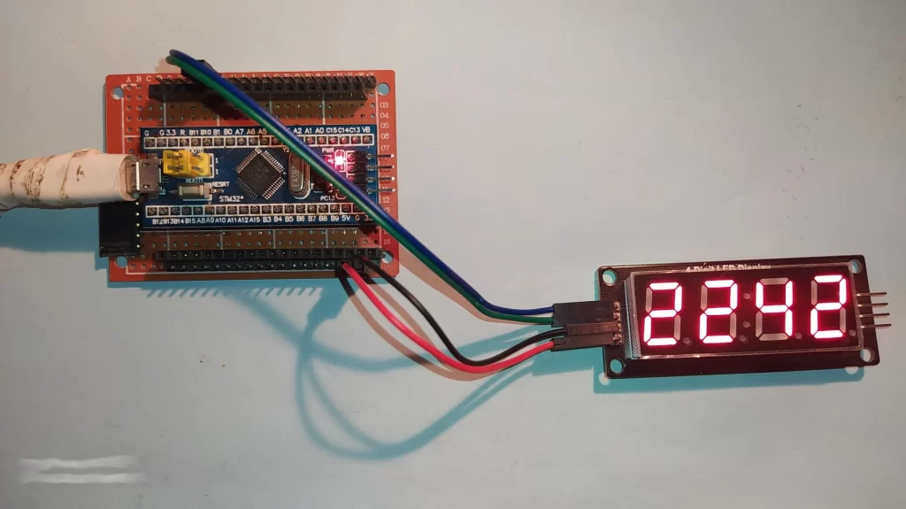
The following video shows my simple DIY circuit:
Proteus Simulation:
The interfacing of ST32F103C8T6 Blue Pill with DHT11 sensor project can be simulated using Proteus simulation software as shown in the video below:
Proteus simulation file download:
Interfacing STM32F103C8T6 Blue Pill with DHT11 sensor and 16×2 LCD Proteus simulation file download link is below, use Proteus version 8.15 or higher to open it.
Download
And the link below is Proteus library for the STM32F103C8T6 Blue Pill board. After the download put the file in Proteus library folder, for example in my case Proteus library folder path is: C:\ProgramData\Labcenter Electronics\Proteus 8 Professional\Library
Proteus library for the STM32F103C8T6 Blue Pill board
Discover more from Simple Circuit
Subscribe to get the latest posts sent to your email.