This STM32 tutorial shows how to easily connect and interface STM32 Blue Pill development board with ST7789 color TFT display module.
The STM32 Blue Pill development board is based on STMicroelectronics ARM Cortex-M3 microcontroller STM32F103C8T6 running at maximum clock frequency of 72MHz. This particular development board gained popularity due to its low cost and compact size, making it a popular choice for hobbyists, students, and developers.
To use the STM32 Blue Pill, a hardware programmer, such as the ST-Link, is required to upload the code to the board. A USB-to-Serial converter module can also be used to upload the code to the board, one example of this converter is the popular one from FTDI which is FT232RL module.
Abbreviations:
TFT: Thin-Film Transistor.
SPI: Serial Peripheral Interface.
IPS: In-Plane Switching.
MOSI: Master Out Slave In.
MISO: Master In Slave Out.
About The ST7789 TFT display:
The ST7789 display is commonly used in projects involving microcontrollers like Arduino or Raspberry Pi. Here are some key features and aspects of the ST7789 display:
- Display Controller: This display is based on a controller IC of the same name, ST7789 (or, ST7789V, ST7789VW), providing an interface between the master device and the display panel.
- Color TFT-LCD: It is specifically designed for color displays, supporting various color depths.
- Resolution: The ST7789 displays come with different resolutions (320×240 pixel, 240×240 pixel…) supporting landscape and portrait orientations.
- Communication Interface: It usually interfaces with microcontrollers or other devices using SPI (Serial Peripheral Interface).
- Supported Operations: The ST7789 TFT display supports standard display operations such as drawing pixels, lines, rectangles, and displaying images.
- Low Power Consumption: It is designed to be power-efficient, suitable for battery-powered or low-power devices.
- Voltage Levels: The ST7789 typically works with various voltage levels, and the specific requirements may vary based on the module or display being used.
- Widely Used in Projects: The ST7789 is often used in DIY electronics projects, especially those involving microcontrollers like Arduino, Raspberry Pi, STM32 Blue Pill, and others.
The following image shows a ST7789 display module provided by Adafruit Industries:

Another version of the ST7789 display module is shown below, it is the one used in this tutorial. This one has no CS (chip select) pin that internally attached to GND. The resolution of this display is 240×240 pixel.
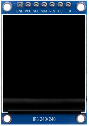
ST7789 TFT display module pin description:
- GND: Ground connection pin
- VCC: Power supply voltage pin
- SCL: Serial Clock pin. Connected to the SPI clock pin of the master device.
- SDA: Serial Data Input pin. Connected to the SPI MOSI (Master Out Slave In) pin of the master device.
- RES: Reset signal pin. Connected to a digital output pin on the master device. It is often optional, and if not used, it could be connected to master device reset pin or tied to a stable low level point.
- DC (Data/Command): Data/Command control signal. Connected to a digital output pin on the master device. It determines whether the data on the bus is a command or actual pixel data.
- BLK (Backlight): Backlight control pin. Connected to a digital output or PWM (Pulse Width Modulation) pin on the master device, it could be connected to VCC for maximum and permanent backlight on the display.
If the display has a CS pin:
- CS: Chip Select pin. Connect to a digital pin on the master device. Used to enable or disable the communication with the ST7789 display.
Hardware Required:
- STM32 Blue Pill board —> STM32F103C8T6 32-bit Arm Cortex-M3 MCU
- ST7789 TFT display module
- Breadboard & jumper wires…
- FTDI FT232RL USB-to-UART converter (for burning program file to the MCU)
Interfacing STM32F103C8T6 Blue Pill with ST7789 TFT display circuit:
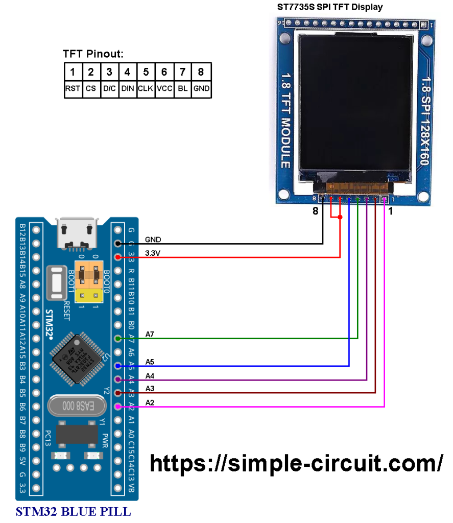
Project circuit schematic diagram is shown below.
The ST7789 display module shown in project circuit diagram has 7 pins: (from left to right): GND (ground), VCC, SCL (serial clock), SDA (serial data), RES (reset), DC (or D/C: data/command) and BLK (back light).
Connecting the BLK pin is optional. The back light turns off when the BLK pin connected to the ground (GND).
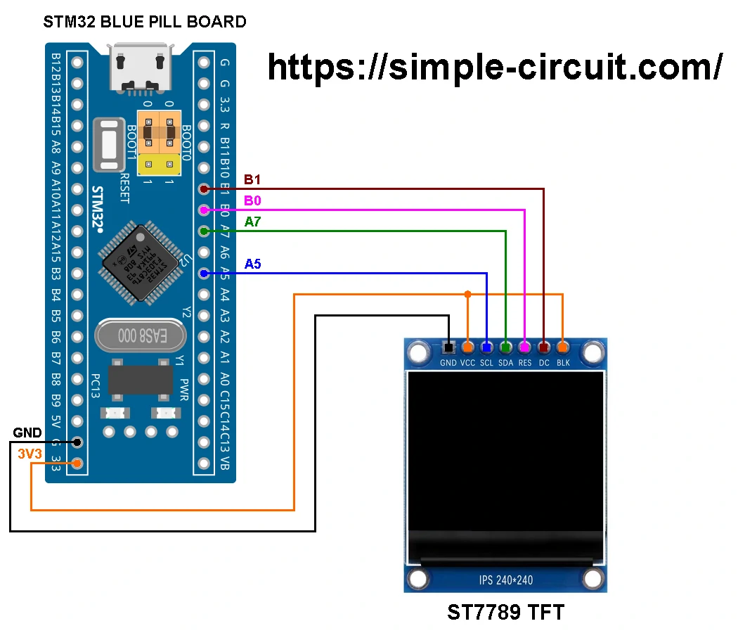
Circuit description:
The main power source of the circuit comes from the micro USB port of the STM32 Blue Pill board with voltage of 5V. The board contains a voltage regulator that feeds the STM32F103C8T6 microcontroller with 3.3V. The ST7789 TFT display module is powered with 3V3 from the STM32 Blue Pill board where its ‘VCC’ & ‘BLK’ pins are connected to ‘3.3V’ pin of the BluePill board.
The ST7789 display is connected to the STM32F103C8T6 Blue Pill board as follows:
GND is connected to pin GND of the Blue Pill board,
VCC and BLK pins are connected to pin 3V3 of the Blue Pill board,
SCL pin is connected to pin PA5 of the Blue Pill board,
SDA pin is connected to pin PA7 of the Blue Pill board,
RST pin is connected to pin PB0 of the Blue Pill board,
DC pin is connected to pin PB1 of the Blue Pill board.
If the display module has a CS pin then it should be connected to pin PA3 of the Blue Pill board.
Pins PA5 and PA7 are hardware SPI1 module pins of the STM32F103C8T6 microcontroller respectively for SCK (serial clock) and MOSI (master-out slave-in).
Interfacing STM32 Blue Pill with ST7789 Display Arduino Code:
Arduino IDE (Integrated Development Environment) is used to write project code, the STM32 Blue Pill board has to be added to the IDE before compilation.
The STM32 Blue Pill board can be installed using Arduino IDE Boards Manager.
Project Arduino code is just an example of graphics test provided by Adafruit Industries with the ST7789 display library.
The FT232RL USB to serial UART converter is used to program the STM32F103C8T6 microcontroller, the ST-LINK V2 programmer also can be used and it is supported by the Arduino IDE.
The following Arduino code requires two libraries from Adafruit Industries:
The first library is a driver for the ST7789 TFT display which can be installed from Arduino IDE library manager (Sketch —> Include Library —> Manage Libraries…, in the search box write “st7789” and install the one from Adafruit).
The second library is Adafruit graphics library which can be installed also from Arduino IDE library manager.
During installation of the Adafruit ST7789 library, Arduino IDE may ask for installing some other libraries form Adafruit Industries (dependencies).
This example code was tested with the following library versions:
Adafruit GFX Library: Version 1.11.9
Adafruit ST7735 and ST7789 Library: Version 1.10.3
Hints:
The used libraries are included in the Arduino code as shown below:
1 2 3 | #include <Adafruit_GFX.h> // Core graphics library #include <Adafruit_ST7789.h> // Hardware-specific library for ST7789 #include <SPI.h> |
The connection between the STM32 Blue Pill board and the ST7789 display is as shown in the above circuit schematic, it is defined in the Arduino code as shown below:
1 2 3 4 | // For the breakout board, you can use any 2 or 3 pins. #define TFT_CS PA4 #define TFT_DC PB1 #define TFT_RST PB0 // Or set to -1 and connect to board RESET pin |
And the initialization of the ST7789 TFT display library with the connections previously defined:
1 | Adafruit_ST7789 tft = Adafruit_ST7789(TFT_CS, TFT_DC, TFT_RST); |
Full Arduino code:
1 2 3 4 5 6 7 8 9 10 11 12 13 14 15 16 17 18 19 20 21 22 23 24 25 26 27 28 29 30 31 32 33 34 35 36 37 38 39 40 41 42 43 44 45 46 47 48 49 50 51 52 53 54 55 56 57 58 59 60 61 62 63 64 65 66 67 68 69 70 71 72 73 74 75 76 77 78 79 80 81 82 83 84 85 86 87 88 89 90 91 92 93 94 95 96 97 98 99 100 101 102 103 104 105 106 107 108 109 110 111 112 113 114 115 116 117 118 119 120 121 122 123 124 125 126 127 128 129 130 131 132 133 134 135 136 137 138 139 140 141 142 143 144 145 146 147 148 149 150 151 152 153 154 155 156 157 158 159 160 161 162 163 164 165 166 167 168 169 170 171 172 173 174 175 176 177 178 179 180 181 182 183 184 185 186 187 188 189 190 191 192 193 194 195 196 197 198 199 200 201 202 203 204 205 206 207 208 209 210 211 212 213 214 215 216 217 218 219 220 221 222 223 224 225 226 227 228 229 230 231 232 233 234 235 236 237 238 239 240 241 242 243 244 245 246 247 248 249 250 251 252 253 254 255 256 257 258 259 260 261 262 263 264 265 266 267 268 269 270 271 272 273 274 275 276 277 278 279 280 281 282 283 284 285 286 287 288 289 290 291 292 293 294 295 296 297 298 299 300 301 302 303 304 305 306 307 308 309 310 311 | /************************************************************************************** * Interfacing STM32F103C8T6 Blue Pill board with ST7789 TFT display (240x240 pixel). * This is a free software with NO WARRANTY. * https://simple-circuit.com/ /************************************************************************************** This is a library for several Adafruit displays based on ST77* drivers. This example works with the 1.14" TFT breakout ----> https://www.adafruit.com/product/4383 The 1.3" TFT breakout ----> https://www.adafruit.com/product/4313 The 1.47" TFT breakout ----> https://www.adafruit.com/product/5393 The 1.54" TFT breakout ----> https://www.adafruit.com/product/3787 The 1.69" TFT breakout ----> https://www.adafruit.com/product/5206 The 1.9" TFT breakout ----> https://www.adafruit.com/product/5394 The 2.0" TFT breakout ----> https://www.adafruit.com/product/4311 Check out the links above for our tutorials and wiring diagrams. These displays use SPI to communicate, 4 or 5 pins are required to interface (RST is optional). Adafruit invests time and resources providing this open source code, please support Adafruit and open-source hardware by purchasing products from Adafruit! Written by Limor Fried/Ladyada for Adafruit Industries. MIT license, all text above must be included in any redistribution *******************************************************************************************/ #include <Adafruit_GFX.h> // Core graphics library #include <Adafruit_ST7789.h> // Hardware-specific library for ST7789 #include <SPI.h> // For the breakout board, you can use any 2 or 3 pins. #define TFT_CS PA4 #define TFT_DC PB1 #define TFT_RST PB0 // Or set to -1 and connect to board RESET pin Adafruit_ST7789 tft = Adafruit_ST7789(TFT_CS, TFT_DC, TFT_RST); float p = 3.1415926; void setup(void) { Serial.begin(9600); Serial.print(F("Hello! ST77xx TFT Test")); // Use this initializer (uncomment) if using a 1.3" or 1.54" 240x240 TFT: tft.init(240, 240, SPI_MODE2); // Init ST7789 240x240 Serial.println(F("Initialized")); // if the screen is flipped, remove this command tft.setRotation(2); uint16_t time = millis(); tft.fillScreen(ST77XX_BLACK); time = millis() - time; Serial.println(time, DEC); delay(500); // large block of text tft.fillScreen(ST77XX_BLACK); testdrawtext("Lorem ipsum dolor sit amet, consectetur adipiscing elit. Curabitur adipiscing ante sed nibh tincidunt feugiat. Maecenas enim massa, fringilla sed malesuada et, malesuada sit amet turpis. Sed porttitor neque ut ante pretium vitae malesuada nunc bibendum. Nullam aliquet ultrices massa eu hendrerit. Ut sed nisi lorem. In vestibulum purus a tortor imperdiet posuere. ", ST77XX_WHITE); delay(1000); // tft print function! tftPrintTest(); delay(4000); // a single pixel tft.drawPixel(tft.width()/2, tft.height()/2, ST77XX_GREEN); delay(500); // line draw test testlines(ST77XX_YELLOW); delay(500); // optimized lines testfastlines(ST77XX_RED, ST77XX_BLUE); delay(500); testdrawrects(ST77XX_GREEN); delay(500); testfillrects(ST77XX_YELLOW, ST77XX_MAGENTA); delay(500); tft.fillScreen(ST77XX_BLACK); testfillcircles(10, ST77XX_BLUE); testdrawcircles(10, ST77XX_WHITE); delay(500); testroundrects(); delay(500); testtriangles(); delay(500); mediabuttons(); delay(500); Serial.println("done"); delay(1000); } void loop() { tft.invertDisplay(true); delay(500); tft.invertDisplay(false); delay(500); } void testlines(uint16_t color) { tft.fillScreen(ST77XX_BLACK); for (int16_t x=0; x < tft.width(); x+=6) { tft.drawLine(0, 0, x, tft.height()-1, color); delay(0); } for (int16_t y=0; y < tft.height(); y+=6) { tft.drawLine(0, 0, tft.width()-1, y, color); delay(0); } tft.fillScreen(ST77XX_BLACK); for (int16_t x=0; x < tft.width(); x+=6) { tft.drawLine(tft.width()-1, 0, x, tft.height()-1, color); delay(0); } for (int16_t y=0; y < tft.height(); y+=6) { tft.drawLine(tft.width()-1, 0, 0, y, color); delay(0); } tft.fillScreen(ST77XX_BLACK); for (int16_t x=0; x < tft.width(); x+=6) { tft.drawLine(0, tft.height()-1, x, 0, color); delay(0); } for (int16_t y=0; y < tft.height(); y+=6) { tft.drawLine(0, tft.height()-1, tft.width()-1, y, color); delay(0); } tft.fillScreen(ST77XX_BLACK); for (int16_t x=0; x < tft.width(); x+=6) { tft.drawLine(tft.width()-1, tft.height()-1, x, 0, color); delay(0); } for (int16_t y=0; y < tft.height(); y+=6) { tft.drawLine(tft.width()-1, tft.height()-1, 0, y, color); delay(0); } } void testdrawtext(char *text, uint16_t color) { tft.setCursor(0, 0); tft.setTextColor(color); tft.setTextWrap(true); tft.print(text); } void testfastlines(uint16_t color1, uint16_t color2) { tft.fillScreen(ST77XX_BLACK); for (int16_t y=0; y < tft.height(); y+=5) { tft.drawFastHLine(0, y, tft.width(), color1); } for (int16_t x=0; x < tft.width(); x+=5) { tft.drawFastVLine(x, 0, tft.height(), color2); } } void testdrawrects(uint16_t color) { tft.fillScreen(ST77XX_BLACK); for (int16_t x=0; x < tft.width(); x+=6) { tft.drawRect(tft.width()/2 -x/2, tft.height()/2 -x/2 , x, x, color); } } void testfillrects(uint16_t color1, uint16_t color2) { tft.fillScreen(ST77XX_BLACK); for (int16_t x=tft.width()-1; x > 6; x-=6) { tft.fillRect(tft.width()/2 -x/2, tft.height()/2 -x/2 , x, x, color1); tft.drawRect(tft.width()/2 -x/2, tft.height()/2 -x/2 , x, x, color2); } } void testfillcircles(uint8_t radius, uint16_t color) { for (int16_t x=radius; x < tft.width(); x+=radius*2) { for (int16_t y=radius; y < tft.height(); y+=radius*2) { tft.fillCircle(x, y, radius, color); } } } void testdrawcircles(uint8_t radius, uint16_t color) { for (int16_t x=0; x < tft.width()+radius; x+=radius*2) { for (int16_t y=0; y < tft.height()+radius; y+=radius*2) { tft.drawCircle(x, y, radius, color); } } } void testtriangles() { tft.fillScreen(ST77XX_BLACK); uint16_t color = 0xF800; int t; int w = tft.width()/2; int x = tft.height()-1; int y = 0; int z = tft.width(); for(t = 0 ; t <= 15; t++) { tft.drawTriangle(w, y, y, x, z, x, color); x-=4; y+=4; z-=4; color+=100; } } void testroundrects() { tft.fillScreen(ST77XX_BLACK); uint16_t color = 100; int i; int t; for(t = 0 ; t <= 4; t+=1) { int x = 0; int y = 0; int w = tft.width()-2; int h = tft.height()-2; for(i = 0 ; i <= 16; i+=1) { tft.drawRoundRect(x, y, w, h, 5, color); x+=2; y+=3; w-=4; h-=6; color+=1100; } color+=100; } } void tftPrintTest() { tft.setTextWrap(false); tft.fillScreen(ST77XX_BLACK); tft.setCursor(0, 30); tft.setTextColor(ST77XX_RED); tft.setTextSize(1); tft.println("Hello World!"); tft.setTextColor(ST77XX_YELLOW); tft.setTextSize(2); tft.println("Hello World!"); tft.setTextColor(ST77XX_GREEN); tft.setTextSize(3); tft.println("Hello World!"); tft.setTextColor(ST77XX_BLUE); tft.setTextSize(4); tft.print(1234.567); delay(1500); tft.setCursor(0, 0); tft.fillScreen(ST77XX_BLACK); tft.setTextColor(ST77XX_WHITE); tft.setTextSize(0); tft.println("Hello World!"); tft.setTextSize(1); tft.setTextColor(ST77XX_GREEN); tft.print(p, 6); tft.println(" Want pi?"); tft.println(" "); tft.print(8675309, HEX); // print 8,675,309 out in HEX! tft.println(" Print HEX!"); tft.println(" "); tft.setTextColor(ST77XX_WHITE); tft.println("Sketch has been"); tft.println("running for: "); tft.setTextColor(ST77XX_MAGENTA); tft.print(millis() / 1000); tft.setTextColor(ST77XX_WHITE); tft.print(" seconds."); } void mediabuttons() { // play tft.fillScreen(ST77XX_BLACK); tft.fillRoundRect(25, 10, 78, 60, 8, ST77XX_WHITE); tft.fillTriangle(42, 20, 42, 60, 90, 40, ST77XX_RED); delay(500); // pause tft.fillRoundRect(25, 90, 78, 60, 8, ST77XX_WHITE); tft.fillRoundRect(39, 98, 20, 45, 5, ST77XX_GREEN); tft.fillRoundRect(69, 98, 20, 45, 5, ST77XX_GREEN); delay(500); // play color tft.fillTriangle(42, 20, 42, 60, 90, 40, ST77XX_BLUE); delay(50); // pause color tft.fillRoundRect(39, 98, 20, 45, 5, ST77XX_RED); tft.fillRoundRect(69, 98, 20, 45, 5, ST77XX_RED); // play color tft.fillTriangle(42, 20, 42, 60, 90, 40, ST77XX_GREEN); } // end of code. |
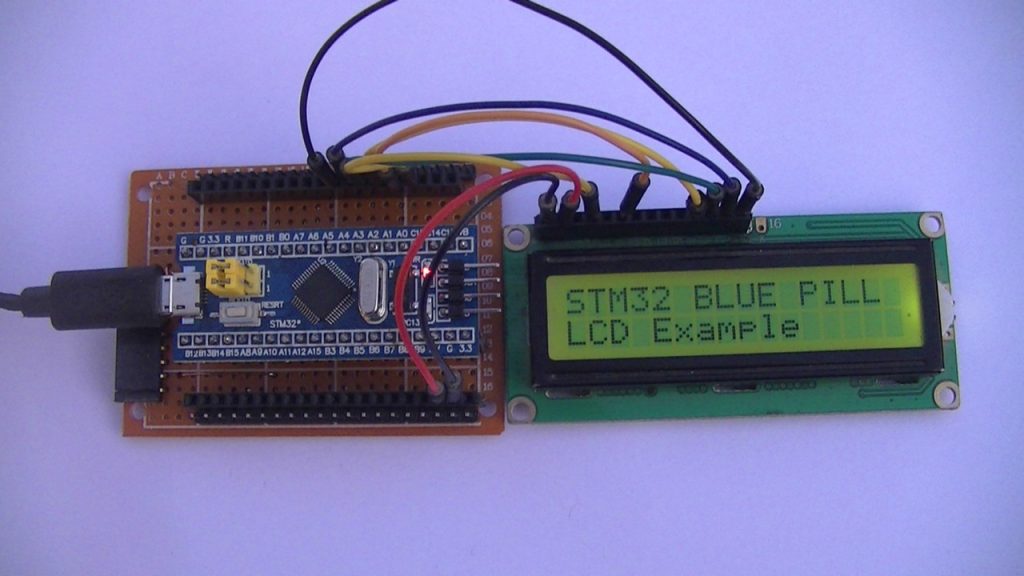
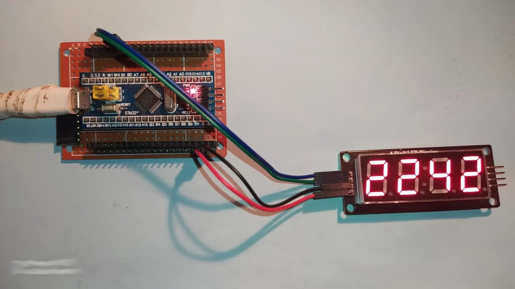
Interfacing STM32 Blue Pill with ST7789 Display Video:
The video below shows my DIY test hardware circuit of a Blue Pill board with ST7789 color display:
Related Projects:
Interfacing STM32 Blue Pill with ST7735 Color TFT Display
Discover more from Simple Circuit
Subscribe to get the latest posts sent to your email.
Doesn’t work! Could You tell versions of libraries used?
Adafruit GFX Library: Version 1.11.9
Adafruit ST7735 and ST7789 Library: Version 1.10.3