This tutorial shows how to connect and interface 8-bit PIC microcontroller family with LCD (Liquid Crystal Display) screens based on HD44780U or compatible controller. Even it is very old, the HD44780U controller or similar is widely used in character type LCD displays which known as 16×2 LCD and 20×4 LCD. A 16×2 (also known as 1602) means that the display has 16 column & 2 rows and it can show up to 32 characters, whereas a 20×4 (also known as 2004) has 20 columns & 4 rows and can show up to 80 characters.
In this post we’ll see how to interface 1602 and 2004 LCDs with different types of Microchip 8-bit PIC microcontrollers, MPLAB XC8 compiler will be used for all examples.
About the HD44780U controller based LCD:
The HD44780U is an integrated circuit (IC) manufactured by Hitachi that is used to control liquid crystal displays (LCDs). It was developed in the 1980s and is still widely used today because of its low cost, versatility, and ease of use.
This type of LCD comes in different sizes depending of number of characters the display can show, the most common types are 16×2 and 20×4.
Some characteristics and features of this type of displays are listed below:
- Character display: The HD44780U controller based LCD modules are primarily designed for displaying alphanumeric characters, symbols, and some other graphical elements.
- Display size: The most popular LCD sizes are the 16×2 (16 characters and 2 lines –> total 32 characters) and 20×4 (20 characters and 4 lines –> total 80 characters), other size are also available such as 16×1…
- Display Interfacing: The HD44780U based display modules typically interface with microcontrollers using either a 4-bit or 8-bit parallel interface. It may be also interfaced using I2C or SPI protocol using another additional module.
- Backlight: Most displays come with integrated backlight LED that improves the visibility in low-light conditions.
- Widely used: Even it is very old type of display (more than 30 years) but it still used in industrial applications, hobbyist and educational projects, instrumentation, consumer electronics…
- Simple Commands: The HD44780U controller based LCD module has a set of very simple commands which makes it very simple to interface with the microcontroller system.
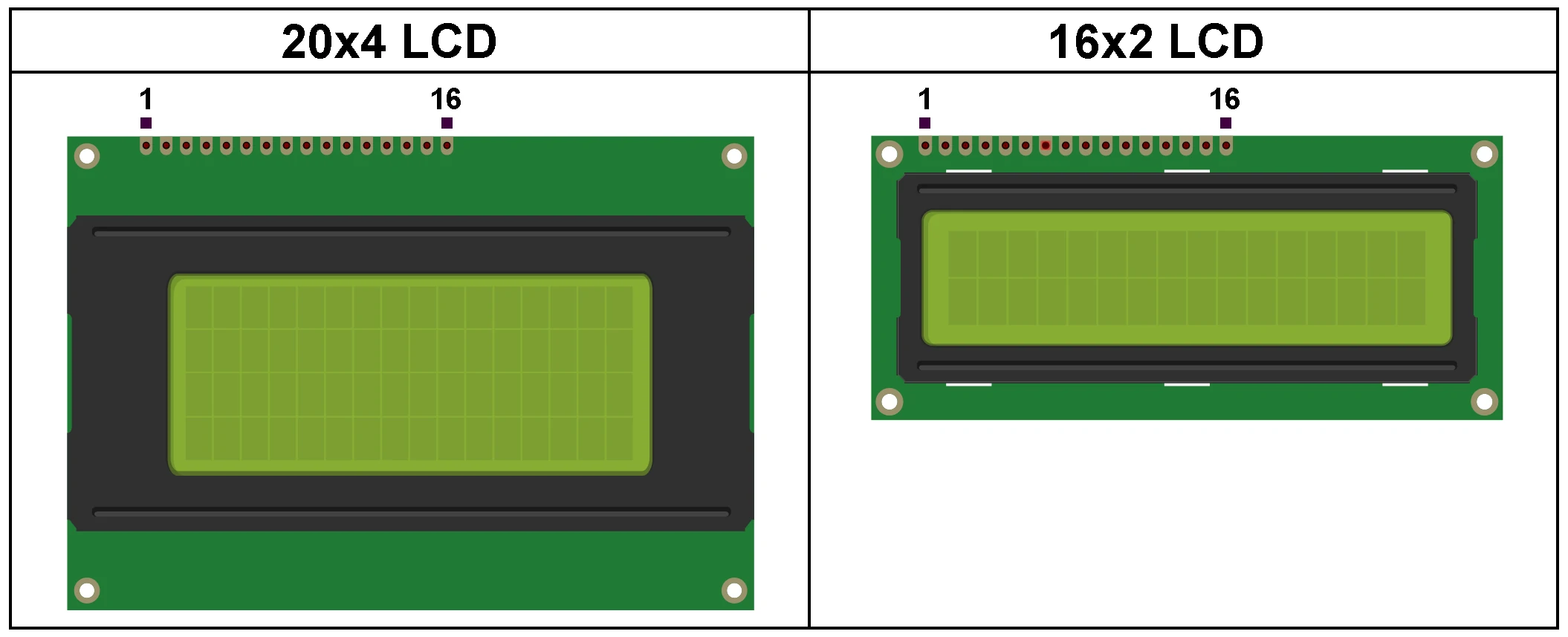
The most popular types of the HD44780 controller display are shown below:
HD44780 Controller LCD pinout:
The 16×2 and 20×4 display modules have the same total number of pins which is 16, they also have the same pinout as described below:
- 1. VSS: Also known as GND (ground), it is ground connection of the LCD module
- 2. VDD: Also known as VCC and it is power supply positive terminal of the module
- 3. V0: Also known as VEE, this pin is used to control the contrast of the display, it is usually connected to a potentiometer or variable resistor output
- 4. RS (Register Select): Selects whether data is being sent to the display is a command (instruction) or a display data. A logic low for command and logic high for display data
- 5. R/W (Read/Write): This pin selects whether data is being read from the display or written to it. Logic high for Read operation and logic low for Write operation. If just write operations are required then this pin could be connected directly to GND
- 6. E (Enable): A pulse input to the enable pin triggers Read/Write operation of the display whatever it is a command or display data
- 7 -10. DB0 to DB3: Four low order bidirectional data pins, used for data transfer between the microcontroller and the LCD. These pins are used only in 8-bit operation and they are not used in 4-bit mode.
- 11-14. DB4 to DB7: Four high order bidirectional data pins, used for data transfer between the microcontroller and the LCD
- 15. A (Anode): This pin is the anode terminal of the backlight LED
- 16. K (Cathode): This is the cathode terminal pin of the backlight LED
Note that the traditional 16×2 and 20×4 LCD modules require power supply with voltage ranging from 4.5V to 5.5V (typically 5V), 3.3V is not sufficient for this type of displays. But when the display is powered with 5V it can read logic high inputs with voltage not less than 2.2V, which means it will work properly with a 3.3V microcontroller if it is supplied with 5 Volts between its VDD and GND pins as what is shown in the example below:
Interfacing STM32 Blue Pill with 1602 LCD
Example 1:
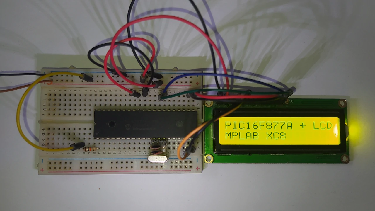
Interfacing PIC16F877A microcontroller with 16×2 LCD:
In the first example, mid-range 8-bit microcontroller PIC16F877A is used. Although more than 20 years is passed from the release of this MCU but it is still in production by Microchip Technology. This microcontroller can run with a maximum clock frequency of 20MHz and achieves 5 MIPS (Million Instruction Per Second). It is very easy to start with which makes it a good choice for beginners who tend to learn PIC microcontrollers, and also it is still used in many application especially educational projects as it contains many integrated peripherals such as:
- 10-Bit Analog-to-Digital Converter (ADC)
- 2 x 10-bit PWM (Pulse Width Modulation) outputs
- 1 x USART (Universal Synchronous Asynchronous Receiver Transmitter)
- 1 x I2C (Inter-Integrated Circuit)
- 1 x SPI (Serial Peripheral Interface)
- 2 x 8-bit Timers (Timer 0 and Timer 1)
- 1 x 16-bit Timer (Timer 1)
PIC16F877A MCU with 16×2 Connection Circuit diagram:
The image below shows a basic circuit schematic of the example, only few components are required.
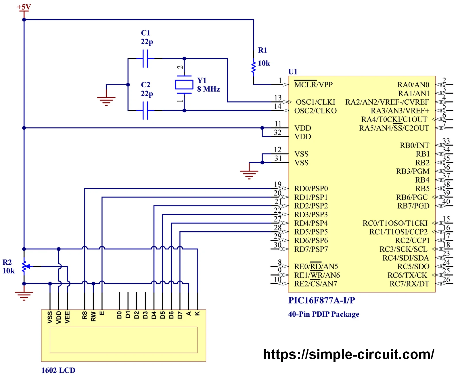
As the PIC16F877A microcontroller has no internal oscillator circuit, a crystal oscillator labeled as Y1 with 8MHz is used as a clock source for the microcontroller. The MCLR pin of the microcontroller is connected to +5V through 10k Ohm resistor (R1).
The microcontroller is supplied with 5 Volts where the positive terminal of the power source is connected to VDD pins (#11 & #32) and the negative terminal is connected to VSS pins (#12 & #32).
The LCD used in this example has 2 lines and 16 columns, its connection is as described below:
VDD & VSS pins are power supply pins of the LCD module where VDD is connected to positive terminal of the power supply and VSS is connected to negative terminal.
VEE Pin (also known as V0) of the LCD module is connected to a 10k Ohm variable resistor output (R2). The usage of the variable resistor allows us to easily control the contrast of the LCD display.
RS (Register Select) Pin is connected to pin RD0 of PIC16F877A microcontroller.
RW (Read/Write) Pin is connected to ground.
E (Enable) Pin of the LCD is connected to pin RD1 of the PIC16F877A MCU.
Data pins, D4, D5, D6, & D7 are respectively connected to MCU pins RD2, RD3, RD4, & RD5.
A and K pins of the LCD are backlight LED anode and cathode terminal, they are respectively connected to GND and +5V.
Pins D0, D1, D2, & D3 are not connected pins because 4-bit mode is used, alternatively, they can be connected to ground.
PIC16F877A MCU with 1602 LCD display MPLAB XC8 compiler C code:
Microchip MPLAB XC8 compiler v2.40 is used in this example, all MPLAB project files including LCD library files can be accessed through the below GitHub link. The readme file in the GitHub link gives all library functions.
Main files of MPLAB XC8 library (driver) for LCD are: lcd.h which is library header file, and lcd.c which is library source code file.
LCD Library for MPLAB XC8 – GitHub
C Code description:
The first lines of example C code is the include of some files including LCD library header file.
1 2 3 4 5 | #include "config.h" // include microcontroller configuration header file #include <xc.h> // include main compiler header file #include <stdio.h> // include stdio header file, required for 'printf' function #include "../lcd.h" // include LCD library header file uint32_t _XTAL_FREQ = 8000000; // set clock frequency to 8 MHz |
The first file config.h contains the setting (values) of the configuration registers with detailed comments. The PIC16F877A microcontroller has one configuration word mapped at address location 2007h.
The second included file is xc.h and it is main compiler header file, it must be included in any project.
The third file is stdio.h which is header file for standard I/O functions, for example the well used printf function.
The last file is lcd.h and it is header file of the LCD library.
As an addition to included files, the clock frequency have to be defined and in our example 8 MHz external crystal oscillator is used.
For the definition of the connection between the microcontroller and the LCD display, another function in main code is used:
1 2 | // set the connection between the MCU and the LCD (&PORTx, RS, E, D4, D5, D6, D7) LCD(&PORTD, 0, 1, 2, 3, 4, 5); |
This simple example shows how to print texts on a 1602 LCD display. The below C code is the main code only, you can find complete MPLAB project files in above GitHub link.
1 2 3 4 5 6 7 8 9 10 11 12 13 14 15 16 17 18 19 20 21 22 23 24 25 26 27 28 29 30 31 32 33 34 35 36 37 38 39 40 41 42 | /***************************************************************** * Interfacing PIC16F877A microcontroller with 1602 LCD screen. * External crystal oscillator used @ 8MHz. * Tested with MPLAB XC8 compiler version v2.40 (C99) with * free optimization level 1. * * This is a free software with NO WARRANTY. * https://simple-circuit.com/ ******************************************************************/ // disable warning 520 (function is never called)! // to enable it just remove or comment the line below #pragma warning disable 520 #include "config.h" // include microcontroller configuration header file #include <xc.h> // include main compiler header file #include <stdio.h> // include stdio header file, required for 'printf' function #include "../lcd.h" // include LCD library header file uint32_t _XTAL_FREQ = 8000000; // set clock frequency to 8 MHz void main(void) { PORTD = 0; TRISD = 0; // configure all port D pins as outputs // set the connection between the MCU and the LCD (&PORTx, RS, E, D4, D5, D6, D7) LCD(&PORTD, 0, 1, 2, 3, 4, 5); // initialize the LCD module with 16 rows and 2 columns (1602 LCD) LCD_Begin(16, 2); // print texts on the display LCD_Goto(1, 1); // move cursor to position (1, 1) --> column = 1 and row = 1 LCD_PutS("PIC16F877A + LCD"); LCD_Goto(1, 2); // move cursor to position (1, 2) --> column = 1 and row = 2 LCD_PutS("MPLAB XC8"); while (1) ; // stay here } // end of code. |
Interfacing PIC16F877A with 16×2 LCD Proteus Simulation Video:
Simulation should be performed before the realization of any project if the required tools are available. Proteus simulation software contains a huge library for electronic circuit simulation and PCB design, the simplicity of its use makes it very popular, especially among students and hobbyists.
I’m adding the following short time video to help understand example much more.
Proteus simulation file download:
Simulation file can be downloaded from the link below, use Proteus version 8.15 or higher to open it.
PIC16F877A + 1602 LCD
Example 2:
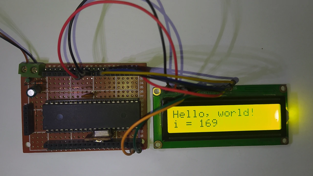
Interfacing PIC18F46K22 microcontroller with 16×2 LCD:
In the second example, PIC18F46K22 is used, this MCU is also an 8-bit microcontroller but it is more advanced than the PIC16F877A.
For more information about the PIC18F46K22 microcontroller just go to its datasheet.
PIC18F46K22 MCU with 16×2 Connection Circuit diagram:
The image below shows a basic circuit schematic of the example, only few components are required.
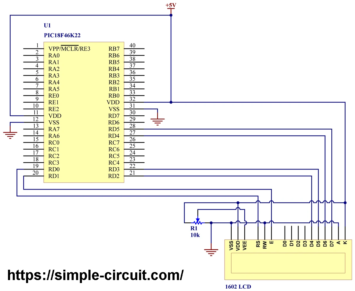
In this example, 5V source is used to power up the PIC18F46K22 MCU and the 1602 LCD display.
For the microcontroller, the positive terminal of the power source is connected to VDD pins (#11 & #32) and the negative terminal is connected to VSS pins (#12 & #32).
The PIC18F46K22 has an internal oscillator which makes the circuit more simpler. External reset functionality of the microcontroller is disabled and RE3 pin (#1) is configured as an input pin.
The LCD used in this example has 2 lines and 16 columns, its connection is as described below:
VDD & VSS pins are power supply pins of the LCD module where VDD is connected to positive terminal of the power supply and VSS is connected to negative terminal.
VEE Pin (also known as V0) of the LCD is connected to a 10k Ohm variable resistor output (R1). The usage of the variable resistor allows us to easily control the contrast of the LCD display.
RS (Register Select) Pin is connected to pin RD0 of PIC18F46K22 microcontroller.
RW (Read/Write) Pin is connected to ground.
E (Enable) Pin of the LCD is connected to pin RD1 of the PIC18F46K22 MCU.
Data pins, D4, D5, D6, & D7 are respectively connected to MCU pins RD2, RD3, RD4, & RD5.
A and K pins of the LCD are backlight LED anode and cathode terminal, they are respectively connected to GND and +5V.
Pins D0, D1, D2, & D3 are not connected pins because 4-bit mode is used, alternatively, they can be connected to ground.
PIC18F46K22 Microcontroller with 1602 LCD display MPLAB XC8 compiler C code:
Microchip MPLAB XC8 compiler v2.40 is used in this example, all MPLAB project files including LCD library files can be accessed through the below GitHub link. The readme file in the GitHub link gives all library functions.
Main files of MPLAB XC8 library (driver) for LCD are: lcd.h which is library header file, and lcd.c which is library source code file.
LCD Library for MPLAB XC8 – GitHub
C Code description:
The first lines of example C code is the include of some files including LCD library header file.
1 2 3 4 5 | #include "config.h" // include microcontroller configuration header file #include <xc.h> // include main compiler header file #include <stdio.h> // include stdio header file, required for 'printf' function #include "../lcd.h" // include LCD library header file uint32_t _XTAL_FREQ = 8000000; // set clock frequency to 8 MHz |
The first file config.h contains the setting (values) of the configuration registers of the PIC18F46K22 microcontroller.
The second included file is xc.h which is main compiler header file, it must be included in any project.
The third file is stdio.h which is header file for standard I/O functions, for example the well used printf function.
The last file is lcd.h and it is header file of the LCD library. The
As an addition to included files, the clock frequency have to be defined and in our example 8 MHz external crystal oscillator is used.
For the definition of the connection between the microcontroller and the LCD display, another function in main code is used:
1 2 | // set the connection between the MCU and the LCD (&PORTx, RS, E, D4, D5, D6, D7) LCD(&PORTD, 0, 1, 2, 3, 4, 5); |
This simple example shows how to print characters, texts, and numbers on a 1602 LCD display. The below C code is the main code only, you can find complete MPLAB project files in above GitHub link.
1 2 3 4 5 6 7 8 9 10 11 12 13 14 15 16 17 18 19 20 21 22 23 24 25 26 27 28 29 30 31 32 33 34 35 36 37 38 39 40 41 42 43 44 45 46 47 48 49 50 51 52 53 54 55 56 57 58 59 60 61 62 63 64 65 66 67 68 69 | /***************************************************************** * Interfacing PIC18F46K22 microcontroller with 1602 LCD screen. * Internal oscillator used @ 8MHz. * Tested with MPLAB XC8 compiler version v2.40 (C99) with * free optimization level 1. * * This is a free software with NO WARRANTY. * https://simple-circuit.com/ ******************************************************************/ // disable warning 520 (function is never called)! // to enable it just remove or comment the line below #pragma warning disable 520 #include "config.h" // include microcontroller configuration header file #include <xc.h> // include main compiler header file #include <stdio.h> // include stdio header file, required for 'printf' function #include "../lcd.h" // include LCD library header file uint32_t _XTAL_FREQ = 8000000; // set clock frequency to 8 MHz // 'putch' function is required for the 'printf' function to work // here it is used to print a character on the LCD using the function 'LCD_PutC' void putch(char c) { LCD_PutC(c); } // main function void main(void) { OSCCON = 0x6C; // use internal oscillator @ 8MHz TRISD = 0; // configure all port D pins as outputs ANSELD = 0; // configure all port D pins as digital pins // set the connection between the MCU and the LCD (&PORTx, RS, E, D4, D5, D6, D7) LCD(&PORTD, 0, 1, 2, 3, 4, 5); // initialize the LCD module with 16 rows and 2 columns (1602 LCD) LCD_Begin(16, 2); // print a list of characters on the display LCD_Goto(1, 1); // move cursor to position (1, 1) --> column = 1 and row = 1 LCD_PutC('L'); LCD_PutC('C'); LCD_PutC('D'); __delay_ms(5000); LCD_Clear(); // clear the display // print a text (string) on the display) LCD_Goto(1, 1); // move cursor to position (1, 1) --> column = 1 and row = 1 LCD_PutS("Hello, world!"); __delay_ms(5000); // print an incremented number using 'printf' function uint8_t i = 0; while (1) { // stay here forever! LCD_Goto(1, 2); // move cursor to position (1, 2) --> column = 1 and row = 2 printf("i = %03u", i); i = i + 1; // increment 'i' by 1 __delay_ms(1000); } } // end of code. |
Interfacing PIC18F46K22 MCU with 16×2 LCD Proteus Simulation Video:
The video below shows the simulation of this example using Proteus ISIS simulation software.
Proteus simulation file download:
Simulation file can be downloaded from the link below, use Proteus version 8.15 or higher to open it.
PIC18F46K22 + 1602 LCD
Example 3:
Interfacing PIC18F46K42 microcontroller with 16×2 LCD:
In the last example, a more newer and advanced 8-bit microcontroller is used which is PIC18F46K42.
For more information about the Microchip PIC18F46K42 microcontroller just go to its datasheet.
In this example two potentiometer connected to PIC18F46K42 microcontroller, POT 1 and POT 2, where the first potentiometer output is connected to analog channel ANA0 (pin #2) and the second potentiometer output is connected to analog channel ANA1 (pin #3).
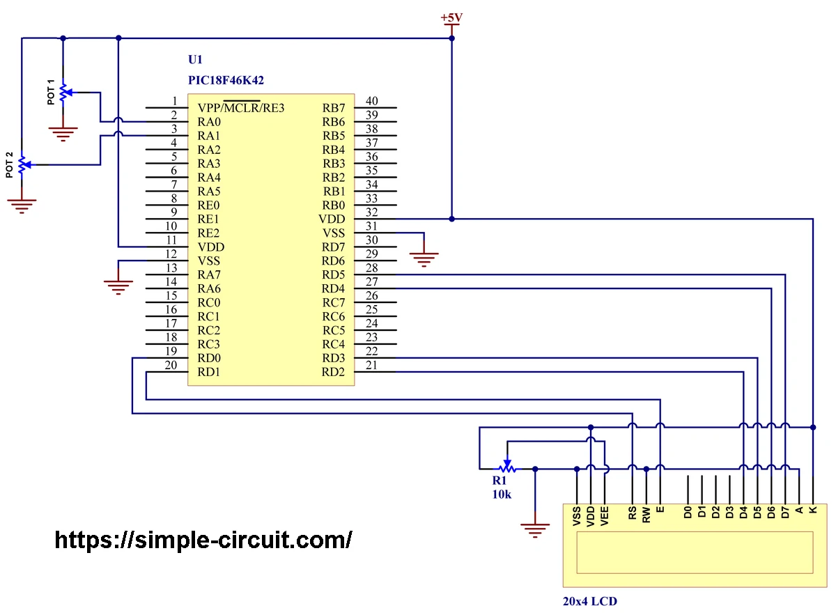
The PIC18F46K42 microcontroller has a built-in analog-to-digital converter (ADC) with resolution of 12 bits. This means digital output value varies between 0 and 4095.
Since the ADC positive reference voltage is VDD (+5V) and negative reference voltage is VSS (0V), a 0V applied to an analog channel is represented by a digital value of 0 and +5V is represented by 4095.
The PIC18F46K42 mcu is powered with 5V where the positive terminal of the power source is connected to VDD pins (#11 & #32) and the negative terminal is connected to VSS pins (#12 & #32).
The PIC18F46K42 has an internal oscillator which makes the circuit more simpler. External reset functionality of the microcontroller is disabled and RE3 pin (#1) is configured as an input pin.
In this example the digital representation of analog output voltage of POT 1 and POT 2 is printed on a 20×4 LCD screen which is connected as follows:
VDD & VSS are power supply pins of the LCD module where VDD is connected to positive terminal of the power supply and VSS is connected to negative terminal.
VEE Pin (also known as V0) of the LCD is connected to a 10k Ohm variable resistor output (R1). The usage of the variable resistor allows us to easily control the contrast of the LCD display.
RS (Register Select) Pin is connected to pin RD0 of PIC18F46K42 microcontroller.
RW (Read/Write) Pin is connected to ground.
E (Enable) Pin of the LCD is connected to pin RD1 of the PIC18F46K42 MCU.
Data pins, D4, D5, D6, & D7 are respectively connected to MCU pins RD2, RD3, RD4, & RD5.
A and K pins of the LCD are backlight LED anode and cathode terminal, they are respectively connected to GND and +5V.
Pins D0, D1, D2, & D3 are not connected pins because 4-bit mode is used, alternatively, they can be connected to ground.
Interfacing PIC18F46K42 Microcontroller with 20×4 LCD display MPLAB XC8 compiler C code:
Microchip MPLAB XC8 compiler v2.40 is used in this example, all MPLAB project files including LCD library files can be accessed through the below GitHub link. The readme file in the GitHub link gives all library functions.
Main files of MPLAB XC8 library (driver) for LCD are: lcd.h which is library header file, and lcd.c which is library source code file.
LCD Library for MPLAB XC8 – GitHub
C Code description:
The first lines of example C code is the include of some files including LCD library header file.
1 2 3 4 5 | #include "config.h" // include microcontroller configuration header file #include <xc.h> // include main compiler header file #include <stdio.h> // include stdio header file, required for 'printf' function #include "../lcd.h" // include LCD library header file uint32_t _XTAL_FREQ = 8000000; // set clock frequency to 8 MHz |
The first file config.h contains the setting (values) of the configuration registers of the PIC18F46K22 microcontroller.
The second included file is xc.h which is main compiler header file, it must be included in any project.
The third file is stdio.h which is header file for standard I/O functions, for example the well used printf function.
The last file is lcd.h and it is header file of the LCD library. The
As an addition to included files, the clock frequency have to be defined and in our example 8 MHz external crystal oscillator is used.
For the definition of the connection between the microcontroller and the LCD display, another function in main code is used:
1 2 | // set the connection between the MCU and the LCD (&PORT, RS, E, D4, D5, D6, D7) LCD(&LATD, 0, 1, 2, 3, 4, 5); |
This LCD example shows how to print characters and texts on the display. It also shows how to read data from analog channel and print its digital representation on the LCD. Main example code is below, full project files including LCD library (driver) for MPLAB XC8 compiler in the above GitHub link.
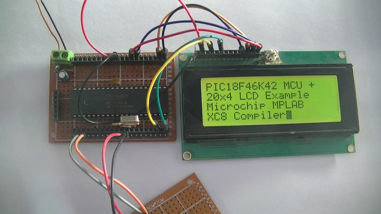
1 2 3 4 5 6 7 8 9 10 11 12 13 14 15 16 17 18 19 20 21 22 23 24 25 26 27 28 29 30 31 32 33 34 35 36 37 38 39 40 41 42 43 44 45 46 47 48 49 50 51 52 53 54 55 56 57 58 59 60 61 62 63 64 65 66 67 68 69 70 71 72 73 74 75 76 77 78 79 80 81 82 83 84 85 86 87 88 89 90 91 92 93 94 95 96 97 98 99 100 101 102 103 104 105 106 107 108 109 110 111 112 113 114 115 116 117 118 119 120 | /***************************************************************** * Interfacing PIC18F46K42 microcontroller with 2004 LCD screen. * Internal oscillator used @ 8MHz. * Tested with MPLAB XC8 compiler version v2.40 (C99) with * free optimization level 1. * * This is a free software with NO WARRANTY. * https://simple-circuit.com/ ******************************************************************/ // disable warning 520 (function is never called)! // to enable it just remove or comment the line below #pragma warning disable 520 #include "config.h" // include microcontroller configuration header file #include <xc.h> // include main compiler header file #include <stdio.h> // include stdio header file, required for 'printf' function #include "../lcd.h" // include LCD library header file uint32_t _XTAL_FREQ = 8000000; // set clock frequency to 8 MHz // 'putch' function is required for the 'printf' function to work // here it is used to print a character on the LCD using the function 'LCD_PutC' void putch(char c) { LCD_PutC(c); } // main function void main(void) { OSCCON1 = 0x60; // Clock source configuration, HFINTOSC, CDIV = 1:1 OSCFRQ = 0x03; // Set internal clock frequency to 8 MHz TRISD = 0; // Initial state of PORTD pins ANSELD = 0; // Configure all PORTD pins as digital // set the connection between the MCU and the LCD (&PORT, RS, E, D4, D5, D6, D7) LCD(&LATD, 0, 1, 2, 3, 4, 5); // initialize the LCD module with 20 rows and 4 columns (20x4 LCD) LCD_Begin(20, 4); LCD_CursorBlink(true); // turn on blinking cursor // print texts on the display LCD_Goto(1, 1); // move cursor to position (1, 1) --> column = 1 and row = 1 LCD_PutS("PIC18F46K42 MCU +"); __delay_ms(2000); LCD_Goto(1, 2); // move cursor to position (1, 2) --> column = 1 and row = 2 LCD_PutS("20x4 LCD Example"); __delay_ms(2000); LCD_Goto(1, 3); // move cursor to position (1, 4) --> column = 1 and row = 3 LCD_PutS("Microchip MPLAB"); __delay_ms(2000); LCD_Goto(1, 4); // move cursor to position (1, 4) --> column = 1 and row = 4 LCD_PutS("XC8 Compiler"); __delay_ms(5000); LCD_Clear(); // clear the display LCD_Goto(7, 1); // move cursor to position (7, 1) --> column = 7 and row = 1 LCD_PutS("LINE 1"); __delay_ms(2000); LCD_Goto(7, 2); // move cursor to position (, 2) --> column = 7 and row = 2 LCD_PutS("LINE 2"); __delay_ms(2000); LCD_Goto(7, 3); // move cursor to position (7, 4) --> column = 7 and row = 3 LCD_PutS("LINE 3"); __delay_ms(2000); LCD_Goto(7, 4); // move cursor to position (7, 4) --> column = 7 and row = 4 LCD_PutS("LINE 4"); __delay_ms(5000); LCD_CursorBlink(false); // turn off blinking cursor LCD_Clear(); // clear the display // ADC Module configuration ADCON0bits.FM = 1; // Right justify of ADC result ADCON0bits.CS = 1; // ADC module uses internal fixed-frequency clock source ADCON0bits.ON = 1; // Turn the ADC module on uint16_t pot1, pot2; LCD_Goto(1, 1); // move cursor to position (1, 1) --> column = 1 and row = 1 LCD_PutS("Potentiometer 1:"); LCD_Goto(1, 3); // move cursor to position (1, 3) --> column = 1 and row = 3 LCD_PutS("Potentiometer 2:"); while (1) { // Get ADC result from POT1 (analog channel ANA0) ADPCH = 0x00; // Select analog channel ANA0 __delay_us(10); // A delay is required between changing channel and start conversion ADCON0bits.GO = 1; // Start conversion while (ADCON0bits.GO); // Wait for the conversion to complete // Store conversion result in the variable 'pot1' where, // ADRESH is result high byte (highest 4 bits), and ADRESL is result low byte (lowest 8 bits) pot1 = ((uint16_t)ADRESH << 8) | ADRESL; // Get ADC result from POT2 (analog channel ANA1) ADPCH = 0x01; // Select analog channel ANA1 __delay_us(10); // A delay is required between changing channel and start conversion ADCON0bits.GO = 1; // Start conversion while (ADCON0bits.GO); // Wait for the conversion to complete // Store conversion result in the variable 'pot1' where, // ADRESH is result high byte (highest 4 bits), and ADRESL is result low byte (lowest 8 bits) pot2 = ((uint16_t)ADRESH << 8) | ADRESL; // Print POT1 and POT2 digital values on the 20x4 LCD LCD_Goto(1, 2); // move cursor to position (1, 1) --> column = 1 and row = 1 printf("%u ", pot1); LCD_Goto(1, 4); // move cursor to position (1, 1) --> column = 1 and row = 1 printf("%u ", pot2); __delay_ms(400); } } // End of code. |
Interfacing PIC18F46K42 microcontroller with 16×2 LCD Video:
This example should work as shown in the following video with DIY hardware circuit:
Discover more from Simple Circuit
Subscribe to get the latest posts sent to your email.