A KS0108 GLCD (Graphics Liquid Crystal Display) refers to a graphical LCD module that utilizes the KS0108 controller chip for controlling the display. This type of GLCD is commonly used in various electronic projects and embedded systems to display graphics, text, and other information.
Actually, the KS0108 took the name from its controller integrated circuit (IC) which is KS0108 mainly designed by Samsung Electronics (KS0108B controller). Here are some key features and information about the KS0108 controller based GLCDs:
- Resolution: The KS0108 controller is often used in displays with a resolution of 64×64, 128×64 or 192×64 pixels where one KS0108 controller can control 64×64 pixels portion. This means it can control 64 columns and 64 rows of pixels. A 128×64 pixel display contains two KS0108 controllers and a display with 192×64 pixels resolution has three controllers.
- Communication: It typically communicates with a microcontroller or microprocessor using a parallel interface with 8-bit data bus. This means it requires several data lines and control lines to send & receive commands and data to the display.
- Graphic Capabilities: The KS0108 controller is well-suited for displaying graphics and text. It allows us to set individual pixels on or off, making it possible to draw lines, shapes, and characters on the screen.
- Voltage Levels: The KS0108 controller often operates at 5V, interfacing it with 3.3V microcontroller may require voltage level shifter (converter).
- Contrast Control: To adjust the contrast of the LCD, a contrast control voltage is usually applied to one of its pins. This allows to make the display more or less readable based on ambient lighting conditions.
- Backlight: Most displays that use the KS0108 controller also include an LED backlight for improved visibility in low-light conditions.
- Applications: Displays with the KS0108 controller are commonly used in embedded systems, instrumentation panels, and DIY electronics projects where graphical information needs to be displayed.
Interfacing a KS0108 GLCD module with a microcontroller system, such as an Arduino or another microcontroller platform, we will typically need to interface it by connecting the appropriate pins to our microcontroller’s GPIO pins and use a suitable library or driver to communicate with the display. The KS0108 LCDs communicates with the microcontroller system using a parallel interface which requires several available (unused) GPIO pins.
The KS0108 GLCD module used in this example has a resolution of 128×64 pixels, it is the one shown below:
![]()
KS0108 GLCD module pin description (numbering starts from right to left):
- VSS: Ground connection pin (GND)
- VDD: Power supply voltage pin (usually 5 Volts)
- VO: Contrast control pin. Connect to a potentiometer to adjust the contrast of the display.
- D/I (Data/Instruction): Data/Command (Instruction) selection pin, also labeled as RS (Register Select). Used to indicate whether data sent to the GLCD is a command or display data, with logic high for display data.
- R/W (Read/Write): Read/Write control pin. Indicates whether data is being read from or written to the GLCD, with logic high for Read operation.
- E (Enable): Enable pin. Used to signal the GLCD that data is ready to be processed.
- DB0 –> DB7 (Data Lines): These are the data lines for display data and commands. DB0 is the least significant bit (LSB), and DB7 is the most significant bit (MSB).
- CS1 (Chip Select 1): Chip select for the left half of the display (for a 128×64 display, the left 64×64 portion).
- CS2 (Chip Select 2): Chip select for the right half of the display (for a 128×64 display, the right 64×64 portion).
- RST (Reset): Reset pin. Used to reset the KS0108 GLCD module, active low.
- VOUT: Negative voltage for LCD bias (usually used for LCD contrast control), also labeled as VEE. The voltage of this pin is usually -5V.
- BLA (Anode): Anode connection for the backlight.
- BLK (Cathode): Cathode connection for the backlight.
Note that the specific pin names and positions can vary between different GLCD modules, so it’s crucial to consult the datasheet or documentation provided by the manufacturer of the GLCD module to ensure accurate connections. Additionally, make sure to connect the pins to the appropriate GPIO pins on the microcontroller system and configure them accordingly in the code to control the GLCD effectively.
The higher resolution GLCD module 192×64 pixels has an additional CS3 (Chip Select 3) pin which is chip select for the most right third of the display (for this display the CS2 (Chip Select 2) pin is chip select for the middle third of the display.
For the chip select pins (CS1, CS2…), the KS0108 GLCD used in this project have an active high chip select pins, but there are some display modules came with active low chip select pins.
Interfacing Arduino with KS0108 GLCD display – Graphics Test Example:
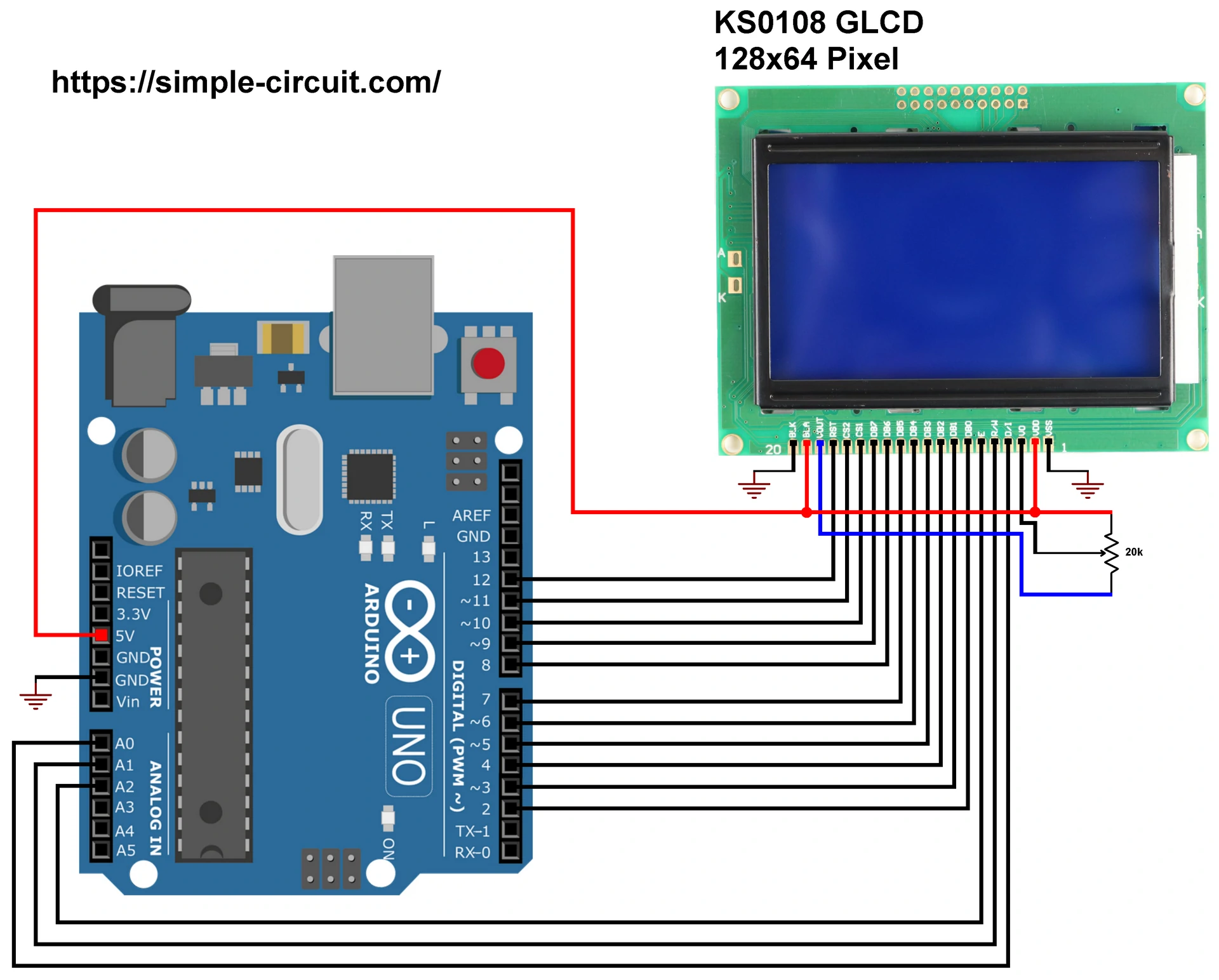
This post shows how to interface Arduino uno R3 board with KS0108 128×64 graphics LCD module, project circuit diagram is shown below.
Hardware Required:
- Arduino board
- KS0108 GLCD with 128×64 pixels resolution module
- 20k ohm variable resistor
- Breadboard
- Jumper wires
Circuit description:
The connection between the KS0108 GLCD module and the Arduino uno Rev 3 board is as described below:
D/I (Data/Instruction) pin is connected to Arduino analog pin 0 (A0).
R/W (Read/Write) pin is connected to Arduino analog pin 1 (A1).
E (enable) pin is connected to Arduino analog pin 2 (A2).
DB0 –> DB7 (Data Lines) are connected to Arduino digital pins 2 –> 9.
CS1 (Chip Select 1) pin is connected to Arduino digital pin 10.
CS2 (Chip Select 2) pin is connected to Arduino digital pin 11.
RST (Reset) pin is connected to Arduino digital pin 12.
VSS (ground) pin and BLK (backlight Cathode) are connected to Arduino GND pin.
VDD (positive power supply) pin and BLA (backlight Anode) are connected to Arduino 5V pin.
The 20k Ohm variable resistor is used to control the contrast of the display, its output is connected to pin VO of the KS0108 GLCD module. The other two pins of the 20k variable resistor are connected to VDD (5V) and VOUT pins of the KS0108 module.
Interfacing Arduino with KS0108 GLCD display code:
To make the interfacing example code more simpler I used an Arduino library for the KS0108 GLCD display. This library works in dependency of Adafruit graphics library (Adafruit_GFX). Both library could be installed online through Arduino Library Manager.
For the KS0108 GLCD library, in the Arduino library manager search box write ‘ks0108’ and install the one published by Simple Circuit as shown in the video below, Arduino IDE may ask for other library installation (“dependencies,” like Adafruit_GFX or Adafruit_BusIO), if they’re not already installed then you have to add them.
The KS0108 GLCD library and Adafruit GFX libraries could be installed offline, GitHub links are below:
KS0108 GLCD library
Adafruit GFX library
The KS0108 GLCD library supports 128×64 and 192×64 pixels resolution displays depending on number of declared CS pins.
For the 192×64 GLCD resolution, the display buffer size is: 192×64/8 = 1536 bytes, and it is stored in RAM space, the Arduino uno microcontroller (ATmega328P) has only 2048 bytes of RAM space which may not be able to allocate RAM space for the display buffer. In any case the begin function will tell us if the compiler successfully allocated a space for the display buffer (returns 1 if OK).
Note that this example was tested with KS0108 GLCD library version 1.0.0 and Adafruit GFX library version 1.11.17.
Code description:
The KS0108 GLCD library contains two graphics test example for the 128×64 and 192×64 pixels resolution. The code below is the test example for the 128×64 pixel display and it was tested with Arduino UNO board and 128×64 pixels KS0108 display module with active high CS pins.
Arduino libraries required for example code are included as shown below:
1 2 | #include <Adafruit_GFX.h> // include adafruit GFX library #include <KS0108_GLCD.h> // include KS0108 GLCD library |
The connection between the KS0108 GLCD and the Arduino is configured in the initialization of the display library:
1 2 3 | // KS0108 GLCD library initialization according to the following connection: // KS0108_GLCD(DI, RW, E, DB0, DB1, DB2, DB3, DB4, DB5, DB6, DB7, CS1, CS2, RES); KS0108_GLCD display = KS0108_GLCD(A0, A1, A2, 2, 3, 4, 5, 6, 7, 8, 9, 10, 11, 12); |
Full Arduino code:
As mentioned above, the Arduino code is the same as the example code that comes with the KS0108 display library with no modification.
1 2 3 4 5 6 7 8 9 10 11 12 13 14 15 16 17 18 19 20 21 22 23 24 25 26 27 28 29 30 31 32 33 34 35 36 37 38 39 40 41 42 43 44 45 46 47 48 49 50 51 52 53 54 55 56 57 58 59 60 61 62 63 64 65 66 67 68 69 70 71 72 73 74 75 76 77 78 79 80 81 82 83 84 85 86 87 88 89 90 91 92 93 94 95 96 97 98 99 100 101 102 103 104 105 106 107 108 109 110 111 112 113 114 115 116 117 118 119 120 121 122 123 124 125 126 127 128 129 130 131 132 133 134 135 136 137 138 139 140 141 142 143 144 145 146 147 148 149 150 151 152 153 154 155 156 157 158 159 160 161 162 163 164 165 166 167 168 169 170 171 172 173 174 175 176 177 178 179 180 181 182 183 184 185 186 187 188 189 190 191 192 193 194 195 196 197 198 199 200 201 202 203 204 205 206 207 208 209 210 211 212 213 214 215 216 217 218 219 220 221 222 223 224 225 226 227 228 229 230 231 232 233 234 235 236 237 238 239 240 241 242 243 244 245 246 247 248 249 250 251 252 253 254 255 256 257 258 259 260 261 262 263 264 265 266 267 268 269 270 271 272 273 274 275 276 277 278 279 280 281 282 283 284 285 286 287 288 289 290 291 292 293 294 295 296 297 298 299 300 301 302 303 304 305 306 307 308 309 310 311 312 313 314 315 316 317 318 319 320 321 322 323 324 325 326 327 328 329 330 331 332 333 334 335 336 337 338 339 340 341 342 343 344 345 346 347 348 349 350 351 352 353 354 355 356 357 358 359 360 361 362 363 364 365 366 367 368 369 370 371 372 373 374 375 376 377 378 379 380 381 382 383 384 385 386 387 388 389 390 391 392 393 394 395 396 397 398 399 400 401 402 403 404 405 406 407 408 409 410 411 412 413 414 415 416 417 418 419 420 421 422 423 424 425 426 427 428 | /********************************************************************************** * * Interfacing Arduino with KS0108 Monochrome GLCD. * This example is for KS0108 GLCD modules with 128x64 Pixel resolution (two CS pins). * This is a free software with NO WARRANTY - Use it at your own risk! * http://simple-circuit.com/ * *********************************************************************************** Written by Limor Fried/Ladyada for Adafruit Industries, with contributions from the open source community. BSD license, check license.txt for more information All text above, and the splash screen below must be included in any redistribution. ************************************************************************************ * Modified to work with KS0108 monochrome GLCD. More information including circuit * diagram on: * http://simple-circuit.com/ * **********************************************************************************/ #include <Adafruit_GFX.h> // include adafruit GFX library #include <KS0108_GLCD.h> // include KS0108 GLCD library // KS0108 GLCD library initialization according to the following connection: // KS0108_GLCD(DI, RW, E, DB0, DB1, DB2, DB3, DB4, DB5, DB6, DB7, CS1, CS2, RES); KS0108_GLCD display = KS0108_GLCD(A0, A1, A2, 2, 3, 4, 5, 6, 7, 8, 9, 10, 11, 12); #define NUMFLAKES 10 // Number of snowflakes in the animation example #define LOGO_HEIGHT 16 #define LOGO_WIDTH 16 static const unsigned char PROGMEM logo_bmp[] = { 0b00000000, 0b11000000, 0b00000001, 0b11000000, 0b00000001, 0b11000000, 0b00000011, 0b11100000, 0b11110011, 0b11100000, 0b11111110, 0b11111000, 0b01111110, 0b11111111, 0b00110011, 0b10011111, 0b00011111, 0b11111100, 0b00001101, 0b01110000, 0b00011011, 0b10100000, 0b00111111, 0b11100000, 0b00111111, 0b11110000, 0b01111100, 0b11110000, 0b01110000, 0b01110000, 0b00000000, 0b00110000 }; void setup() { Serial.begin(9600); // initialize KS0108 GLCD module with active high CS pins if ( display.begin(KS0108_CS_ACTIVE_HIGH) == false ) { Serial.println( F("display initialization failed!") ); // lack of RAM space while(true); // stay here forever! } display.display(); delay(2000); // Pause for 2 seconds // Clear the buffer display.clearDisplay(); // Draw a single pixel in white display.drawPixel(10, 10, KS0108_ON); // Show the display buffer on the screen. You MUST call display() after // drawing commands to make them visible on screen! display.display(); delay(2000); // display.display() is NOT necessary after every single drawing command, // unless that's what you want...rather, you can batch up a bunch of // drawing operations and then update the screen all at once by calling // display.display(). These examples demonstrate both approaches... testdrawline(); // Draw many lines testdrawrect(); // Draw rectangles (outlines) testfillrect(); // Draw rectangles (filled) testdrawcircle(); // Draw circles (outlines) testfillcircle(); // Draw circles (filled) testdrawroundrect(); // Draw rounded rectangles (outlines) testfillroundrect(); // Draw rounded rectangles (filled) testdrawtriangle(); // Draw triangles (outlines) testfilltriangle(); // Draw triangles (filled) testdrawchar(); // Draw characters of the default font testdrawstyles(); // Draw 'stylized' characters testscrolltext(); // Draw scrolling text display.invertDisp(true); display.display(); delay(1000); display.invertDisp(false); display.display(); delay(1000); testdrawbitmap(); // Draw a small bitmap image testanimate(logo_bmp, LOGO_WIDTH, LOGO_HEIGHT); // Animate bitmaps } // main loop (nothing here!) void loop() { } void testdrawline() { int16_t i; display.clearDisplay(); // Clear display buffer for(i=0; i<display.width(); i+=4) { display.drawLine(0, 0, i, display.height()-1, KS0108_ON); display.display(); // Update screen with each newly-drawn line delay(1); } for(i=0; i<display.height(); i+=4) { display.drawLine(0, 0, display.width()-1, i, KS0108_ON); display.display(); delay(1); } delay(250); display.clearDisplay(); for(i=0; i<display.width(); i+=4) { display.drawLine(0, display.height()-1, i, 0, KS0108_ON); display.display(); delay(1); } for(i=display.height()-1; i>=0; i-=4) { display.drawLine(0, display.height()-1, display.width()-1, i, KS0108_ON); display.display(); delay(1); } delay(250); display.clearDisplay(); for(i=display.width()-1; i>=0; i-=4) { display.drawLine(display.width()-1, display.height()-1, i, 0, KS0108_ON); display.display(); delay(1); } for(i=display.height()-1; i>=0; i-=4) { display.drawLine(display.width()-1, display.height()-1, 0, i, KS0108_ON); display.display(); delay(1); } delay(250); display.clearDisplay(); for(i=0; i<display.height(); i+=4) { display.drawLine(display.width()-1, 0, 0, i, KS0108_ON); display.display(); delay(1); } for(i=0; i<display.width(); i+=4) { display.drawLine(display.width()-1, 0, i, display.height()-1, KS0108_ON); display.display(); delay(1); } delay(2000); // Pause for 2 seconds } void testdrawrect(void) { display.clearDisplay(); for(int16_t i=0; i<display.height()/2; i+=2) { display.drawRect(i, i, display.width()-2*i, display.height()-2*i, KS0108_ON); display.display(); // Update screen with each newly-drawn rectangle delay(1); } delay(2000); } void testfillrect(void) { display.clearDisplay(); for(int16_t i=0; i<display.height()/2; i+=3) { // The INVERSE color is used so rectangles alternate white/KS0108_ON display.fillRect(i, i, display.width()-i*2, display.height()-i*2, KS0108_INVERSE); display.display(); // Update screen with each newly-drawn rectangle delay(1); } delay(2000); } void testdrawcircle(void) { display.clearDisplay(); for(int16_t i=0; i<max(display.width(),display.height())/2; i+=2) { display.drawCircle(display.width()/2, display.height()/2, i, KS0108_ON); display.display(); delay(1); } delay(2000); } void testfillcircle(void) { display.clearDisplay(); for(int16_t i=max(display.width(),display.height())/2; i>0; i-=3) { // The INVERSE color is used so circles alternate white/black display.fillCircle(display.width() / 2, display.height() / 2, i, KS0108_INVERSE); display.display(); // Update screen with each newly-drawn circle delay(1); } delay(2000); } void testdrawroundrect(void) { display.clearDisplay(); for(int16_t i=0; i<display.height()/2-2; i+=2) { display.drawRoundRect(i, i, display.width()-2*i, display.height()-2*i, display.height()/4, KS0108_ON); display.display(); delay(1); } delay(2000); } void testfillroundrect(void) { display.clearDisplay(); for(int16_t i=0; i<display.height()/2-2; i+=2) { // The INVERSE color is used so round-rects alternate white/KS0108_ON display.fillRoundRect(i, i, display.width()-2*i, display.height()-2*i, display.height()/4, KS0108_INVERSE); display.display(); delay(1); } delay(2000); } void testdrawtriangle(void) { display.clearDisplay(); for(int16_t i=0; i<max(display.width(),display.height())/2; i+=5) { display.drawTriangle( display.width()/2 , display.height()/2-i, display.width()/2-i, display.height()/2+i, display.width()/2+i, display.height()/2+i, KS0108_ON); display.display(); delay(1); } delay(2000); } void testfilltriangle(void) { display.clearDisplay(); for(int16_t i=max(display.width(),display.height())/2; i>0; i-=5) { // The INVERSE color is used so triangles alternate white/black display.fillTriangle( display.width()/2 , display.height()/2-i, display.width()/2-i, display.height()/2+i, display.width()/2+i, display.height()/2+i, KS0108_INVERSE); display.display(); delay(1); } delay(2000); } void testdrawchar(void) { display.clearDisplay(); display.setTextSize(1); // Normal 1:1 pixel scale display.setTextColor(KS0108_ON); // Draw white text display.setCursor(0, 0); // Start at top-left corner display.cp437(true); // Use full 256 char 'Code Page 437' font // Not all the characters will fit on the display. This is normal. // Library will draw what it can and the rest will be clipped. for(int16_t i=0; i<256; i++) { if(i == '\n') display.write(' '); else display.write(i); } display.display(); delay(2000); } void testdrawstyles(void) { display.clearDisplay(); display.setTextSize(1); // Normal 1:1 pixel scale display.setTextColor(KS0108_ON); // Draw white text display.setCursor(0,0); // Start at top-left corner display.println(F("Hello, world!")); display.setTextColor(KS0108_OFF, KS0108_ON); // Draw 'inverse' text display.println(3.141592); display.setTextSize(2); // Draw 2X-scale text display.setTextColor(KS0108_ON); display.print(F("0x")); display.println(0xDEADBEEF, HEX); display.display(); delay(2000); } void testscrolltext(void) { display.clearDisplay(); display.setTextSize(2); // Draw 2X-scale text display.setTextColor(KS0108_ON); display.setCursor(10, 0); display.println(F("scroll")); display.display(); // Show initial text delay(1000); // Scroll in various directions, pausing in-between: // scroll right for (uint8_t scroll = 0; scroll < 0x0F; scroll++) { display.scrollRight(1); display.display(); delay(10); } delay(1000); // scroll left for (uint8_t scroll = 0; scroll < 0x0F; scroll++) { display.scrollLeft(1); display.display(); delay(10); } delay(1000); // diagonal scroll right-up for (uint8_t scroll = 0; scroll < display.height()/2; scroll++) { display.scrollRight(1); display.scrollUp(1); display.display(); delay(10); } delay(1000); // diagonal scroll left-up for (uint8_t scroll = 0; scroll < display.height()/2; scroll++) { display.scrollLeft(1); display.scrollUp(1); display.display(); delay(10); } delay(1000); } void testdrawbitmap(void) { display.clearDisplay(); display.drawBitmap( (display.width() - LOGO_WIDTH ) / 2, (display.height() - LOGO_HEIGHT) / 2, logo_bmp, LOGO_WIDTH, LOGO_HEIGHT, 1); display.display(); delay(1000); } #define XPOS 0 // Indexes into the 'icons' array in function below #define YPOS 1 #define DELTAY 2 void testanimate(const uint8_t *bitmap, uint8_t w, uint8_t h) { int8_t f, icons[NUMFLAKES][3]; // Initialize 'snowflake' positions for(f=0; f< NUMFLAKES; f++) { icons[f][XPOS] = random(1 - LOGO_WIDTH, display.width()); icons[f][YPOS] = -LOGO_HEIGHT; icons[f][DELTAY] = random(1, 6); Serial.print(F("x: ")); Serial.print(icons[f][XPOS], DEC); Serial.print(F(" y: ")); Serial.print(icons[f][YPOS], DEC); Serial.print(F(" dy: ")); Serial.println(icons[f][DELTAY], DEC); } for(;;) { // Loop forever... display.clearDisplay(); // Clear the display buffer // Draw each snowflake: for(f=0; f< NUMFLAKES; f++) { display.drawBitmap(icons[f][XPOS], icons[f][YPOS], bitmap, w, h, KS0108_ON); } display.display(); // Show the display buffer on the screen delay(200); // Pause for 1/10 second // Then update coordinates of each flake... for(f=0; f< NUMFLAKES; f++) { icons[f][YPOS] += icons[f][DELTAY]; // If snowflake is off the bottom of the screen... if (icons[f][YPOS] >= display.height()) { // Reinitialize to a random position, just off the top icons[f][XPOS] = random(1 - LOGO_WIDTH, display.width()); icons[f][YPOS] = -LOGO_HEIGHT; icons[f][DELTAY] = random(1, 6); } } } } // end of code. |
Interfacing Arduino with KS0108 GLCD Video:
This example was tested with Arduino NANO in a DIY hardware circuit as shown in the video below:
Interfacing Arduino with KS0108 GLCD Proteus Simulation Video:
We can simulate this project using Proteus simulation software since it contains the KS0108 device simulation library. Simulation result for the Arduino UNO board with a 128×64 pixel KS0108 display is in the following video:
A simulation also for a 192×64 pixel display with Arduino MEGA board is shown in the video below:
Arduino with KS0108 GLCD Proteus simulation file download:
Proteus simulation file of the two above examples can be downloaded from the below Google Drive link. Use Proteus version 8.15 or higher to open it.
DOWNLOAD
Discover more from Simple Circuit
Subscribe to get the latest posts sent to your email.


OK to Arduino Nano
please, the code does for the 19264 version is not available… can i get that one?
Hi
Thank you so much for your good explanations’ about KS0108B and a perfectly guide on interfacing a KS0108 Graphics LCD with an Arduino .
I have a problem with my 240×64 pixels resolution GLCD with RA6963 controller chip (with part no. p079 rev:d pg24643 ).
I connected the glcd to my arduino uno and check for some library for RA6963 but i couldn’t get good result.
Would you please guide me about the suitable library to used this glcd and Interfacing with Arduino uno . Iam waitting for your kind response.
thanks
best regards
shahram
Hi many thanks for the code first of all.
after doing a long and cramps intense soldering session I managed to connect everything and upload your code successfully.
Now I see only a blue screen, for the contrast voltage I used the 3,3 V output of the Arduino.
Could this be the fault?
Do I really need a variable resistor?
You almost always need a variable resistor. The working voltage range of the actual LCD is quite narrow, too little and it just stays blank, too much and it goes all black or all white.
If you look at the BLUE wire on the diagram it goes from a pin marked VOUT to the contrast pot, the display will be outputting about minus 5 volts (typically).
The LCD voltage is the difference between the positive supply and the contrast supply. I looked up the voltage for a NEWHAVEN DISPLAY module and the total LCD voltage at room temp is about 8V (7.8V to 8.2).
If the positive supply is 5V then Vo needs to be minus 3 volts.
By far the easiest way is to use an adjustment pot.
By the way if the display was running from 3.3V you may be able to make it work by supplying Vo with 3.3V-8V= minus 4.7V. The Vout pin would be producing only minus 3.3V though.
I did design a circuit that didn’t have a variable resistor for contrast, instead I took a PWM output from the microcontroller, and used an op-amp to smooth it and invert it to give zero to minus five volts, programmable. My reasoning was that having an adustment slot looked untidy but to be honest it was a bit of a “flex”.
thanks for the great tutorial. I have a problem. the microcontroller I’m gonna use for a project is an stm32 with 3.3V working voltages, and this module works with 5V. I have 5V rail in my circuit, and I know I can go the voltage-translation way, but I’ve come to conclusion that I better (kinda have to) use a 74HC245 IC to translate my stm32 outputs of 3.3V to 5V required by GLCD. but this way I can only send data from MCU to GLCD. can’t read data from GLCD.
so the question is : Do I need to read data from GLCD at all? (assuming I can program my MCU so that I know what’s currently shown on the LCD. can I get away with always sending data to LCD and never reading anything from it ?)
I’m not 100% certain but I’m fairly confident the graphics library is write-only. It is hard to be certain as the R/W line is implemented but there seems to be a trend towards storing a bitmap in Microcontroller RAM and only ever writing to the display.
Looking at the KS0108B datasheet on Sparkfun the device’s interface pins have lowered input thresholds compatible with 3.3V logic, so it does not need a buffer to raise the signals to 5V levels.
In the other direction the STM32 might have a 5V tolerant port, it isn’t uncommon for some of a 3.3V microcontroller’s I/O to be 5V tolerant.
Another possibility is that while the KS0108B is described as a 5V+/-10% part some other controllers like the nt7108 support 3.3v operation. 3.3V operation would avoid the need for another supply rail too.
The most obvious clue is the display PCB has space for a second charge pump IC. On the 5V version one IC develops -5V on Vout, on the 3.3V version two charge pumps are used to develop -6.6V enabling contrast to be maintained. Contrast is set by the difference between VDD and VO regardless of the exact VDD value, a feature which is very useful when VDD is variable (battery projects).
Ecelent!
This is a fantastic guide on interfacing a KS0108 Graphics LCD with an Arduino! I appreciate the detailed explanation of the KS0108 controller and its features, as well as the step-by-step instructions for connecting the GLCD to the Arduino board.