This post shows the interfacing process of Arduino uno board with ST7565 monochrome 128×64 LCD display. This example shows how to print texts, draw bitmap images and some shapes (such as lines, circles …) on the ST7565 LCD.
Basically, The ST7565 is a popular LCD controller chip manufactured by Sitronix Technology Corporation. It is commonly used in small graphical LCD modules, often found in applications such as industrial equipment, consumer electronics, and DIY projects. The ST7565 controller is known for its compatibility with various microcontrollers and ease of use for displaying graphics and text.
Here are some key features and characteristics of the ST7565 LCD controller:
- Controller Type: ST7565 is a monochrome (usually black and white) graphical LCD controller.
- Resolution: The commonly used resolution for the ST7565 controller based display is 128×64 pixel, but other LCDs with resolution such as 128×32 could be found.
- Communication Interface: The ST7565 uses parallel interface or serial interface (SPI protocol) for communication with the microcontroller. This means it requires several GPIO pins to transfer data and commands. The parallel interface requires more pins than the serial SPI interface.
- Display Modes: It supports both text and graphical modes, making it suitable for a wide range of applications.
- Built-in RAM: The ST7565 controller typically has an internal display buffer (RAM) that it is used to store graphics and text before being displayed on the screen.
- Voltage Requirements: Basically the ST7565 controller itself works only with 3.3V. LCD modules usually require a supply voltage of around 3.3V or 5V, depending on the specific module and configuration.
- Backlighting: Usually LCD modules come with LED backlighting for improved visibility in low-light conditions.
- Controller Commands: ST7565 controllers accept various commands for controlling display functions, such as setting the display contrast, addressing individual pixels, and more.
To use an ST7565 LCD module with a microcontroller, we will typically need to interface it by connecting the appropriate pins to our microcontroller’s GPIO pins and use a suitable library or driver to communicate with the display. In this example SPI (Serial Peripheral Interface) communication protocol interface is used which requires 5 GPIO pins at maximum.
The ST7565 LCD module used in this example is the one shown below (GMG12864-06D):
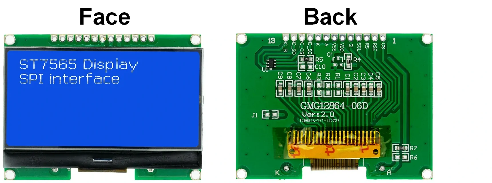
The ST7565 LCD used in this project has 13 pins numbered from right to left as shown in the above image. The LCD module also contains a small 6-pin integrated circuit (IC) labeled as U1, this IC named as 16S1Y and it is used to get simplified Chinese character set font in 15×16 dot size, this IC also works with SPI communication protocol and connected to the microcontroller via 4-wire interface. The 16S1Y IC is not used in this project.
ST7565 LCD module pin description (numbering starts from right to left seeing from module back view):
- CS: chip select pin, active low
- RES: controller reset pin, active low
- RS: register select pin, also named as A0
- SCL: serial clock signal input, also labeled as SCK
- SI: serial data input pin, also labeled as SDA or MOSI (Master Out Slave In)
- VDD: positive power supply pin
- VSS: negative (ground) power supply pin
- A: backlight LED anode terminal pin
- K: backlight LED cathode terminal pin
- IC_SCL: 16S1Y IC serial clock signal input pin
- IC_CS: 16S1Y IC chip select pin
- IC_SO: 16S1Y IC serial data output pin
- IC_SI: 16S1Y IC serial data input pin
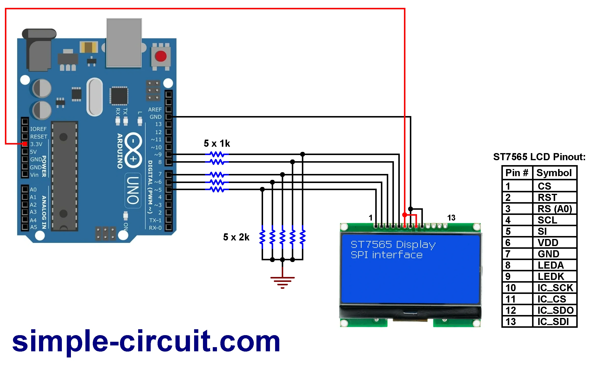
Basically, the ST7565 controller works with 3.3V, applying a voltage of 5 Volts may damage it. The same thing applied to the LCD module I’m using in this example, we should use 3.3V both for power supply and control signals, connection of the LCD with the Arduino board is as shown in project circuit diagram below.
Hardware Required:
- Arduino UNO R3, or equivalent board —> ATmega328P microcontroller datasheet
- ST7565 LCD module
- 5 x 2k ohm resistor
- 5 x 1k ohm resistor
- Breadboard
- Jumper wires
Interfacing Arduino with ST7565 LCD display circuit:
Project circuit diagram is shown below, the connection between the Arduino UNO R3 board and the ST7565 LCD module is very simple.
Circuit description:
The connection between the Arduino uno Rev 3 board and the ST7565 LCD is very simple, only 5 GPIO pins are required.
As mentioned above, the ST7565 LCD display works only with 3.3V, applying a 5V directly to the display module may harm its controller circuit. In this project the ST7565 LCD module is powered directly from the Arduino board with 3.3V where VDD pin of the LCD (#6) is connected to Arduino 3.3V pin and GND pin of the LCD (#7) is connected to Arduino GND pin.
For the 5 control signal connection between the Arduino board and the ST7565 LCD, I used voltage divider circuit for each control signal to get a suitable voltage for the LCD. Each voltage divider consists of 1k and 2k resistors and they are connected as shown in the circuit diagram above.
By applying voltage divider equation and assuming a 5V output from the Arduino board we get: 5 x 2/(2+1) = 3.33V which is very nice voltage value for the LCD.
The ST7565 LCD module is connected to the Arduino board as follows (each control pin connected to Arduino through voltage divider):
CS: connected to Arduino digital pin 5
RES: connected to Arduino digital pin 6
RS (A0): connected to Arduino digital pin 7
SCL(SCK): connected to Arduino digital pin 8
SI(SDA, MOSI): connected to Arduino digital pin 9
VDD: connected to Arduino 3.3V pin
GND: connected to Arduino GND pin
LEDA: connected to Arduino 3.3V pin
LEDK: connected to Arduino GND pin
Other pins: Not connected
The not connected pins are for the 16S1Y IC which is not used in this project.
LEDA & LEDK are LCD backlight LED pins.
Note that with this connection software SPI is used and it is configured in project Arduino code.
Interfacing Arduino with ST7565 LCD display code:
To make the interfacing example code more simpler I used an Arduino library for the ST7565 LCD display. This library works in dependency of Adafruit graphics library (Adafruit_GFX). Both library could be installed online through Arduino Library Manager.
For the ST7565 LCD, in the Arduino library manager search box write ‘st7565’ and install the one published by Simple Circuit, Arduino IDE may ask for other library installation (“dependencies,” like Adafruit_GFX or Adafruit_BusIO), if thery’re not already installed then you have to add them.
The ST7565 LCD library and Adafruit GFX libraries could be installed offline, GitHub links are below:
ST7565 LCD library
Adafruit GFX library
Note that this example was tested with ST7565 library version 1.0.2 and Adafruit GFX library version 1.11.17.
Code description:
Arduino libraries needed for project code are included as shown below:
1 2 3 | #include <SPI.h> #include <Adafruit_GFX.h> #include <ST7565_LCD.h> |
The connection between the ST7565 LCD and the Arduino are defined as:
1 2 3 4 5 6 | // ST7565 LCD connection with Arduino board using software SPI #define LCD_DIN 9 #define LCD_SCLK 8 #define LCD_A0 7 #define LCD_RESET 6 #define LCD_CS 5 |
And the ST7565 library is configured and initialized as below, with this configuration software SPI is used:
1 | ST7565_LCD display = ST7565_LCD(LCD_DIN, LCD_SCLK, LCD_A0, LCD_RESET, LCD_CS); |
Full Arduino code:
1 2 3 4 5 6 7 8 9 10 11 12 13 14 15 16 17 18 19 20 21 22 23 24 25 26 27 28 29 30 31 32 33 34 35 36 37 38 39 40 41 42 43 44 45 46 47 48 49 50 51 52 53 54 55 56 57 58 59 60 61 62 63 64 65 66 67 68 69 70 71 72 73 74 75 76 77 78 79 80 81 82 83 84 85 86 87 88 89 90 91 92 93 94 95 96 97 98 99 100 101 102 103 104 105 106 107 108 109 110 111 112 113 114 115 116 117 118 119 120 121 122 123 124 125 126 127 128 129 130 131 132 133 134 135 136 137 138 139 140 141 142 143 144 145 146 147 148 149 150 151 152 153 154 155 156 157 158 159 160 161 162 163 164 165 166 167 168 169 170 171 172 173 174 175 176 177 178 179 180 181 182 183 184 185 186 187 188 189 190 191 192 193 194 195 196 197 198 199 200 201 202 203 204 205 206 207 208 209 210 211 212 213 214 215 216 217 218 219 220 221 222 223 224 225 226 227 228 229 230 231 232 233 234 235 236 237 238 239 240 241 242 243 244 245 246 247 248 249 250 251 252 253 254 255 256 257 258 259 260 261 262 263 264 265 266 267 268 269 270 271 272 273 274 275 276 277 278 279 280 281 282 283 284 285 286 287 288 289 290 291 292 293 294 295 296 297 298 299 300 301 302 303 304 305 306 307 308 309 310 311 312 313 314 315 316 317 318 319 320 321 322 323 324 325 326 327 328 329 330 331 332 333 334 335 336 337 338 339 340 341 342 343 344 345 346 347 348 349 350 351 352 353 354 355 356 357 358 359 360 361 362 363 364 365 366 367 368 369 370 371 372 373 374 375 376 377 378 379 380 381 382 383 384 385 386 387 388 389 390 391 392 393 394 395 396 397 398 399 400 401 402 403 404 405 406 407 408 409 410 411 412 413 414 415 416 417 418 419 420 421 422 423 424 425 426 427 428 429 430 431 432 433 434 435 436 437 438 439 440 441 442 443 444 445 446 447 448 449 450 451 452 453 454 455 456 457 458 459 460 461 462 463 464 465 466 467 468 469 470 471 472 473 474 475 476 477 478 479 480 481 482 483 484 485 486 487 488 489 490 491 492 493 494 495 496 497 498 | /********************************************************************************** * * Interfacing Arduino with ST7565 Monochrome LCD (128x64 Pixel) * This is a free software with NO WARRANTY - Use it at your own risk! * http://simple-circuit.com/ * *********************************************************************************** Written by Limor Fried/Ladyada for Adafruit Industries, with contributions from the open source community. BSD license, check license.txt for more information All text above, and the splash screen below must be included in any redistribution. ************************************************************************************ Modified to work with ST7565 Monochrome LCD. http://simple-circuit.com/ **********************************************************************************/ #include <SPI.h> #include <Adafruit_GFX.h> #include <ST7565_LCD.h> // ST7565 LCD connection with Arduino board using software SPI #define LCD_DIN 9 #define LCD_SCLK 8 #define LCD_A0 7 #define LCD_RESET 6 #define LCD_CS 5 ST7565_LCD display = ST7565_LCD(LCD_DIN, LCD_SCLK, LCD_A0, LCD_RESET, LCD_CS); /*/ Comment out above, uncomment this block to use hardware SPI // connect LCD 'DIN' & 'SCLK' to board's hardware SPI pins #define LCD_A0 7 #define LCD_RESET 6 #define LCD_CS 5 ST7565 display = ST7565(LCD_A0, LCD_RESET, LCD_CS); */ #define NUMFLAKES 10 // Number of snowflakes in the animation example #define LOGO_HEIGHT 16 #define LOGO_WIDTH 16 static const unsigned char PROGMEM logo_bmp[] = { 0b00000000, 0b11000000, 0b00000001, 0b11000000, 0b00000001, 0b11000000, 0b00000011, 0b11100000, 0b11110011, 0b11100000, 0b11111110, 0b11111000, 0b01111110, 0b11111111, 0b00110011, 0b10011111, 0b00011111, 0b11111100, 0b00001101, 0b01110000, 0b00011011, 0b10100000, 0b00111111, 0b11100000, 0b00111111, 0b11110000, 0b01111100, 0b11110000, 0b01110000, 0b01110000, 0b00000000, 0b00110000 }; void setup() { Serial.begin(9600); // initialize the ST7565 LCD display with contrast = 13 (0 <= coontrast <= 63) display.begin(13); display.display(); delay(2000); // Pause for 2 seconds testscrolldisplay(); // scroll whole display in different directions // Clear the buffer display.clearDisplay(); // Draw a single pixel in white display.drawPixel(10, 10, ST7565_ON); // Show the display buffer on the screen. You MUST call display() after // drawing commands to make them visible on screen! display.display(); delay(2000); // display.display() is NOT necessary after every single drawing command, // unless that's what you want...rather, you can batch up a bunch of // drawing operations and then update the screen all at once by calling // display.display(). These examples demonstrate both approaches... testdrawline(); // Draw many lines testdrawrect(); // Draw rectangles (outlines) testfillrect(); // Draw rectangles (filled) testdrawcircle(); // Draw circles (outlines) testfillcircle(); // Draw circles (filled) testdrawroundrect(); // Draw rounded rectangles (outlines) testfillroundrect(); // Draw rounded rectangles (filled) testdrawtriangle(); // Draw triangles (outlines) testfilltriangle(); // Draw triangles (filled) testdrawchar(); // Draw characters of the default font testdrawstyles(); // Draw 'stylized' characters testscrolltext(); // Draw scrolling text testdrawbitmap(); // Draw a small bitmap image // Invert and restore display, pausing in-between display.invertDisplay(true); delay(1000); display.invertDisplay(false); delay(1000); testanimate(logo_bmp, LOGO_WIDTH, LOGO_HEIGHT); // Animate bitmaps } // main loop (nothing here!) void loop() { } void testscrolldisplay() { // scroll right for (uint8_t scroll = 0; scroll < display.width(); scroll++) { display.scrollRight(1); // scroll the screen to the right by '1' pixel display.display(); delay(10); // wait 10 ms } delay(1000); // wait for 1 second // scroll left for (uint8_t scroll = 0; scroll < display.width(); scroll++) { display.scrollLeft(1); // scroll the screen to the left by '1' pixel display.display(); delay(10); // wait 10 ms } delay(1000); // wait for 1 second // scroll up for (uint8_t scroll = 0; scroll < display.height(); scroll++) { display.scrollUp(1); // scroll the screen to the left by '1' pixel display.display(); delay(10); // wait 10 ms } delay(1000); // wait for 1 second // scroll down for (uint8_t scroll = 0; scroll < display.height(); scroll++) { display.scrollDown(1); // scroll the screen to the left by '1' pixel display.display(); delay(10); // wait 10 ms } delay(1000); // wait for 1 second // scroll diagonal right-up for (uint8_t scroll = 0; scroll < display.width(); scroll++) { display.scrollRight(1); // scroll the screen to the right by '1' pixel display.scrollUp(1); // scroll the screen to the left by '1' pixel display.display(); delay(10); // wait 10 ms } delay(1000); // wait for 1 second // scroll diagonal right-down for (uint8_t scroll = 0; scroll < display.width(); scroll++) { display.scrollRight(1); // scroll the screen to the right by '1' pixel display.scrollDown(1); // scroll the screen to the left by '1' pixel display.display(); delay(10); // wait 10 ms } delay(1000); // wait for 1 second // scroll diagonal left-up for (uint8_t scroll = 0; scroll < display.width(); scroll++) { display.scrollLeft(1); // scroll the screen to the right by '1' pixel display.scrollUp(1); // scroll the screen to the left by '1' pixel display.display(); delay(10); // wait 10 ms } delay(1000); // wait for 1 second // scroll diagonal left-down for (uint8_t scroll = 0; scroll < display.width(); scroll++) { display.scrollLeft(1); // scroll the screen to the right by '1' pixel display.scrollDown(1); // scroll the screen to the left by '1' pixel display.display(); delay(10); // wait 10 ms } delay(1000); // wait for 1 second } void testdrawline() { int16_t i; display.clearDisplay(); // Clear display buffer for(i=0; i<display.width(); i+=4) { display.drawLine(0, 0, i, display.height()-1, ST7565_ON); display.display(); // Update screen with each newly-drawn line delay(1); } for(i=0; i<display.height(); i+=4) { display.drawLine(0, 0, display.width()-1, i, ST7565_ON); display.display(); delay(1); } delay(250); display.clearDisplay(); for(i=0; i<display.width(); i+=4) { display.drawLine(0, display.height()-1, i, 0, ST7565_ON); display.display(); delay(1); } for(i=display.height()-1; i>=0; i-=4) { display.drawLine(0, display.height()-1, display.width()-1, i, ST7565_ON); display.display(); delay(1); } delay(250); display.clearDisplay(); for(i=display.width()-1; i>=0; i-=4) { display.drawLine(display.width()-1, display.height()-1, i, 0, ST7565_ON); display.display(); delay(1); } for(i=display.height()-1; i>=0; i-=4) { display.drawLine(display.width()-1, display.height()-1, 0, i, ST7565_ON); display.display(); delay(1); } delay(250); display.clearDisplay(); for(i=0; i<display.height(); i+=4) { display.drawLine(display.width()-1, 0, 0, i, ST7565_ON); display.display(); delay(1); } for(i=0; i<display.width(); i+=4) { display.drawLine(display.width()-1, 0, i, display.height()-1, ST7565_ON); display.display(); delay(1); } delay(2000); // Pause for 2 seconds } void testdrawrect(void) { display.clearDisplay(); for(int16_t i=0; i<display.height()/2; i+=2) { display.drawRect(i, i, display.width()-2*i, display.height()-2*i, ST7565_ON); display.display(); // Update screen with each newly-drawn rectangle delay(1); } delay(2000); } void testfillrect(void) { display.clearDisplay(); for(int16_t i=0; i<display.height()/2; i+=3) { // The INVERSE color is used so rectangles alternate white/ST7565_ON display.fillRect(i, i, display.width()-i*2, display.height()-i*2, ST7565_INVERSE); display.display(); // Update screen with each newly-drawn rectangle delay(1); } delay(2000); } void testdrawcircle(void) { display.clearDisplay(); for(int16_t i=0; i<max(display.width(),display.height())/2; i+=2) { display.drawCircle(display.width()/2, display.height()/2, i, ST7565_ON); display.display(); delay(1); } delay(2000); } void testfillcircle(void) { display.clearDisplay(); for(int16_t i=max(display.width(),display.height())/2; i>0; i-=3) { // The INVERSE color is used so circles alternate white/black display.fillCircle(display.width() / 2, display.height() / 2, i, ST7565_INVERSE); display.display(); // Update screen with each newly-drawn circle delay(1); } delay(2000); } void testdrawroundrect(void) { display.clearDisplay(); for(int16_t i=0; i<display.height()/2-2; i+=2) { display.drawRoundRect(i, i, display.width()-2*i, display.height()-2*i, display.height()/4, ST7565_ON); display.display(); delay(1); } delay(2000); } void testfillroundrect(void) { display.clearDisplay(); for(int16_t i=0; i<display.height()/2-2; i+=2) { // The INVERSE color is used so round-rects alternate white/ST7565_ON display.fillRoundRect(i, i, display.width()-2*i, display.height()-2*i, display.height()/4, ST7565_INVERSE); display.display(); delay(1); } delay(2000); } void testdrawtriangle(void) { display.clearDisplay(); for(int16_t i=0; i<max(display.width(),display.height())/2; i+=5) { display.drawTriangle( display.width()/2 , display.height()/2-i, display.width()/2-i, display.height()/2+i, display.width()/2+i, display.height()/2+i, ST7565_ON); display.display(); delay(1); } delay(2000); } void testfilltriangle(void) { display.clearDisplay(); for(int16_t i=max(display.width(),display.height())/2; i>0; i-=5) { // The INVERSE color is used so triangles alternate white/black display.fillTriangle( display.width()/2 , display.height()/2-i, display.width()/2-i, display.height()/2+i, display.width()/2+i, display.height()/2+i, ST7565_INVERSE); display.display(); delay(1); } delay(2000); } void testdrawchar(void) { display.clearDisplay(); display.setTextSize(1); // Normal 1:1 pixel scale display.setTextColor(ST7565_ON); // Draw white text display.setCursor(0, 0); // Start at top-left corner display.cp437(true); // Use full 256 char 'Code Page 437' font // Not all the characters will fit on the display. This is normal. // Library will draw what it can and the rest will be clipped. for(int16_t i=0; i<256; i++) { if(i == '\n') display.write(' '); else display.write(i); } display.display(); delay(2000); } void testdrawstyles(void) { display.clearDisplay(); display.setTextSize(1); // Normal 1:1 pixel scale display.setTextColor(ST7565_ON); // Draw white text display.setCursor(0,0); // Start at top-left corner display.println(F("Hello, world!")); display.setTextColor(ST7565_OFF, ST7565_ON); // Draw 'inverse' text display.println(3.141592); display.setTextSize(2); // Draw 2X-scale text display.setTextColor(ST7565_ON); display.print(F("0x")); display.println(0xDEADBEEF, HEX); display.display(); delay(2000); } void testscrolltext(void) { display.clearDisplay(); display.setTextSize(2); // Draw 2X-scale text display.setTextColor(ST7565_ON); display.setCursor(10, 0); display.println(F("scroll")); display.display(); // Show initial text delay(1000); // Scroll in various directions, pausing in-between: // scroll right for (uint8_t scroll = 0; scroll < 0x0F; scroll++) { display.scrollRight(1); display.display(); delay(10); } delay(1000); // scroll left for (uint8_t scroll = 0; scroll < 0x0F; scroll++) { display.scrollLeft(1); display.display(); delay(10); } delay(1000); // diagonal scroll right-up for (uint8_t scroll = 0; scroll < display.height()/2; scroll++) { display.scrollRight(1); display.scrollUp(1); display.display(); delay(10); } delay(1000); // diagonal scroll left-up for (uint8_t scroll = 0; scroll < display.height()/2; scroll++) { display.scrollLeft(1); display.scrollUp(1); display.display(); delay(10); } delay(1000); } void testdrawbitmap(void) { display.clearDisplay(); display.drawBitmap( (display.width() - LOGO_WIDTH ) / 2, (display.height() - LOGO_HEIGHT) / 2, logo_bmp, LOGO_WIDTH, LOGO_HEIGHT, 1); display.display(); delay(1000); } #define XPOS 0 // Indexes into the 'icons' array in function below #define YPOS 1 #define DELTAY 2 void testanimate(const uint8_t *bitmap, uint8_t w, uint8_t h) { int8_t f, icons[NUMFLAKES][3]; // Initialize 'snowflake' positions for(f=0; f< NUMFLAKES; f++) { icons[f][XPOS] = random(1 - LOGO_WIDTH, display.width()); icons[f][YPOS] = -LOGO_HEIGHT; icons[f][DELTAY] = random(1, 6); Serial.print(F("x: ")); Serial.print(icons[f][XPOS], DEC); Serial.print(F(" y: ")); Serial.print(icons[f][YPOS], DEC); Serial.print(F(" dy: ")); Serial.println(icons[f][DELTAY], DEC); } for(;;) { // Loop forever... display.clearDisplay(); // Clear the display buffer // Draw each snowflake: for(f=0; f< NUMFLAKES; f++) { display.drawBitmap(icons[f][XPOS], icons[f][YPOS], bitmap, w, h, ST7565_ON); } display.display(); // Show the display buffer on the screen delay(200); // Pause for 1/10 second // Then update coordinates of each flake... for(f=0; f< NUMFLAKES; f++) { icons[f][YPOS] += icons[f][DELTAY]; // If snowflake is off the bottom of the screen... if (icons[f][YPOS] >= display.height()) { // Reinitialize to a random position, just off the top icons[f][XPOS] = random(1 - LOGO_WIDTH, display.width()); icons[f][YPOS] = -LOGO_HEIGHT; icons[f][DELTAY] = random(1, 6); } } } } // end of code. |
Interfacing Arduino with ST7565 LCD Video:
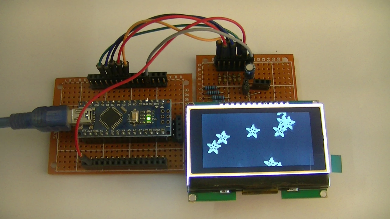
The following video shows my DIY project circuit:
Interfacing Arduino with ST7565 LCD Proteus Simulation Video:
We can simulate this project using Proteus simulation software since it contains ST7565 device library. Simulation result as shown in this video.
Arduino with ST7565 LCD Proteus simulation file download:
Proteus simulation file of this project can be downloaded from the below Google Drive link. Use Proteus version 8.15 or higher to open it.
DOWNLOAD
Discover more from Simple Circuit
Subscribe to get the latest posts sent to your email.


Hello, i try it, it work for me, but i have a question:
Why lcd is not user in all SCREEN? I have the same result that the video youtube
Thanks for the nice work.Can you make an example of this screen that we can use in CCS C?