Isolation in electrical engineering involves separating one part of a circuit from another to avoid direct physical electrical connection, allowing signals and power to be transferred without a direct conductive path to prevent accidental contact, protect sensitive electronics, and ensure safe operation.
Purpose of Circuit Isolation:
- Safety: Most important purpose. High voltage can be dangerous, and isolation helps protecting people from coming into direct contact with high voltage circuits. Isolation also protects components by isolating high-voltage parts from low-voltage parts.
- Noise Reduction: Isolation can help reducing electrical noise and interference between different circuit sections.
- Signal Integrity: Maintains the quality of signals by preventing crosstalk and ground loops.
- Fault Protection: Limits the spread of faults, such as short circuits, to other parts of the system.
Electrical Isolation Methods:
There are several methods of electrical isolation, some of them are listed below.
- Optical Isolation: Use light to transfer signals across an insulating barrier. An LED on one side and a photodetector on the other side provide electrical isolation. The main component that achieve optical isolation is the Optocoupler (Optoisolator).
- Magnetic Isolation: Transformers transfer energy from one side to the other side through magnetic fields. Used in power supplies and signal isolation transformers.
- Capacitive Isolation: Capacitors allow AC signals to pass while blocking DC, providing isolation in AC signal paths.
- Electromechanical Isolation: Relays and contactors provide physical separation between control and power circuits.
Isolated DC Voltage Measurement with Arduino and HCNR201 Optocoupler:
This post shows how to build a precision isolated high voltage DC sensing circuit based on Arduino board and HCNR201 (or HCNR200) optocoupler. DC Voltage values are printed on 1602 LCD screen and sent to Arduino IDE serial monitor tool.
Hints:
- No warranty is provided with this project, so do it at your own risk!
- A part of project circuit may be subjected to a high voltage level which is very harmful to human body, so be-careful!
High voltage side of the circuit is isolated from low voltage side using the HCNR201 optocoupler.
The HCNR201 optocoupler used in the circuit to make a unity gain analog isolation amplifier. More details about the HCNR201 optocoupler in this post:
Precision Analog Isolation Amplifier Using HCNR201 Optocoupler
Isolated DC Voltage Measurement Circuit:
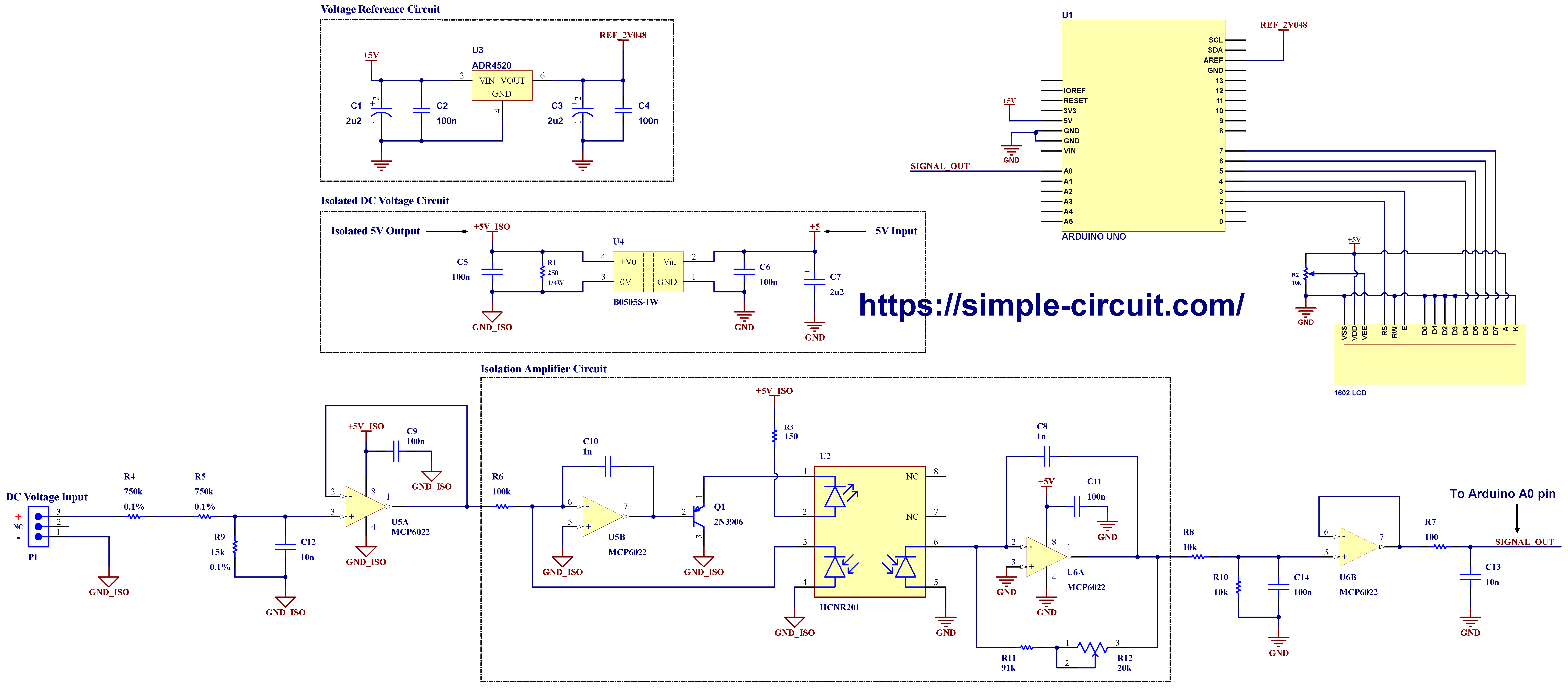
Project circuit diagram is shown below (click on the image to show in high resolution view).
Hardware Required:
- Arduino UNO board (or similar), (U1) —> Board info <—> ATmega328P datasheet
- HCNR201 (or HCNR200) optocoupler (U2) —> datasheet
- ADR4520 2.048 voltage reference (U3) —> details
- B0505-1W Isolated DC/DC converter (U4) —> datasheet
- 2 x MCP6022 operational amplifier (U5, U6) —> datasheet
- 1602 LCD screen
- 2N3906 PNP transistor (Q1)
- 250 Ohm, 1/4 W resistor (R1)
- 10k Ohm variable resistor (R2)
- 150 Ohm resistor (R3)
- 2 x 750k Ohm resistor (R4, R5)
- 100k Ohm resistor (R6)
- 100 Ohm resistor (R7)
- 2 x 10k Ohm resistor (R8, R10)
- 15k Ohm resistor (R9)
- 91k Ohm resistor (R11)
- 20k Ohm variable resistor (R12), type: 3296W-1-203
- 3 x 16V, 2u2 electrolytic capacitor (C1, C3, C7)
- 7 x 100n ceramic capacitor (C2, C4, C5, C6, C9, C11, C14)
- 2 x 1n ceramic capacitor (C8, C10)
- 2 x 10n ceramic capacitor (C12, C13)
- Three position connector (P1)
Circuit Description:
The DC voltage to measure terminals is indicated in the circuit diagram as ‘DC Voltage Input’ where a three-position screw connector is used to easily connect the voltage source to the circuit. Theoretically, we can apply a DC voltage up to 400 Volts.
A resistive voltage divider is used to step down the input high voltage. This voltage divider consists of resistors: R4, R5, and R9, by applying voltage divider formula we get an attenuation factor equals to: 15k/(750k + 750k + 15k) = 15/1515 = 1/101.
This means an applied voltage of 400VDC will be attenuated to: 400/101 = 3.96V .
Resistors R4 & R5 should be through hole type with power rating not less than 1/4W, voltage rating should not be less than 250V. Tolerance of the three resistors of the voltage divider should be 0.1% or better.
The capacitor C12 (10nF) with voltage divider resistors R4 (750k), R5 (750k), and R9 (15k) forms a low pass filter, the cutoff frequency can be calculated as follows:
fc = 1/(2π∗Req∗C)
where: Req = (R4+R5)//R9 = 1500k // 15k = 14.85k
===> fc = 1/(2π ∗ 14.85k ∗ 10n) = 1071 Hz
The attenuated and filtered voltage signal passes through voltage follower using the op amp U5A (MCP6022 dual op amp), and then it enters the isolation amplifier circuit that is based on the HCNR201 optocoupler. Since the isolation amplifier circuit has unity gain, its output voltage always equals to the input voltage.
Note that HCNR200 optocoupler can be used instead of HCNR201.
The output signal of the isolation amplifier finally passes through active low pass filter and also attenuated again with coefficient of 2, this means an input voltage of 4V will be attenuated to 2V. The cutoff frequency of this low pass filter is:
fc = 1/(2π ∗ 5k ∗ 100n) = 318 Hz
Op amp U6B voltage follower provides low source impedance for the Arduino ADC (Analog-to-Digital Converter) module. A final stage passive low pass filter using resistor R7 and capacitor C13 is used to eliminate high frequency noise, the cutoff frequency is:
fc = 1/(2π ∗ 100 ∗ 10n) = 159 kHz
At this point, the input signal is attenuated with factor of: 1/(101 x 2) = 1/202. For example, an input DC voltage of 300V will be dropped to 300/202 = 1.485V, and this voltage is the one applied to Arduino analog channel.
Isolated DC Voltage Circuit:
To satisfy the isolation property between the input signal and the output signal, the input signal power supply must be isolated from the output signal power supply. For this purpose I used an isolated DC-to-DC converter which annotated in the circuit schematic as U4. In this project I used MORNSUN B0505-1W low cost unregulated DC/DC converter with 5V input and 5V output, other equivalents such as RECOM RFM-0505S (–datasheet–) can be used. Using an isolated DC/DC converter provides a galvanic isolation between the input voltage and the output voltage.
The input power supply voltage of the circuit is 5V, it comes from the Arduino board. The non-isolated 5V power terminals are +5V and GND.
The isolated 5V source comes from the isolated DC/DC converter (U4) with +5V_ISO (Isolated +5V) is positive and GND_ISO (Isolated Ground) is negative. Note that there is no direct physical connection between GND and GND_ISO.
The components placed in the high voltage side of the circuit are supplied with isolated power supply, whereas the low voltage side components are supplied directly from the Arduino board.
ADC Voltage Reference:
I used the ADR4520 ultra low noise, high accuracy 2.048V voltage reference IC manufactured by Analog Devices to get a stable and accurate voltage of 2.048V, which is then used as a positive voltage reference for the Arduino microcontroller ADC module. The output of the ADR4520 is directly connected to Arduino AREF pin.
The 1602 LCD screen (2 rows and 16 columns) is used to display AC voltage & frequency values, it is connected to the Arduino board as follows:
RS —> Arduino digital pin 2
E —> Arduino digital pin 3
D4 —> Arduino digital pin 4
D5 —> Arduino digital pin 5
D6 —> Arduino digital pin 6
D7 —> Arduino digital pin 7
VSS, D0, D1, D2, D3 and K are connected to GND,
VEE to the 10k Ohms variable resistor (or potentiometer) output,
Pins VDD & A to Arduino 5V.
VEE pin is used to control the contrast of the LCD. A (anode) and K (cathode) are back light LED pins.
Isolated DC Voltage Measurement with Arduino Code:
Project Arduino code is the one below, it was tested with Arduino NANO board.
The values of applied DC voltage are printed on 16×2 LCD and Arduino IDE serial monitor tool.
Programming hints:
The Arduino UNO and similar boards microcontroller (ATmega328P) has a built-in 10-bit ADC module, this means the digital representation of any analog signal is within the range [0, 1023]. As we have a positive reference voltage of 2.048V (supplied by ADR4520), analog signal voltage applied to Arduino analog channel should be in the range [0, 2.048V] where a zero volt is represented by digital value of 0 and 2.048V is represented by digital value of 1023.
The ADC of the Arduino is configured to be auto-triggered by Timer1 Compare Match-B every 1 millisecond, this means we have a sample rate of 1000 samples per second (1ksps).
The displayed DC voltage value is updated every 250ms (4 times per second) so that the Arduino takes 250 samples and averaging them to get more accurate, stable, and precise values.
Rest of code is described through comments.
Full Arduino code:
1 2 3 4 5 6 7 8 9 10 11 12 13 14 15 16 17 18 19 20 21 22 23 24 25 26 27 28 29 30 31 32 33 34 35 36 37 38 39 40 41 42 43 44 45 46 47 48 49 50 51 52 53 54 55 56 57 58 59 60 61 62 63 64 65 66 67 68 69 70 71 72 73 74 75 76 77 78 79 80 81 82 83 84 85 86 87 88 | /******************************************************************************* * * Isolated DC voltage measurement with Arduino. * Calculated voltage values are printed on 1602 LCD screen and serial monitor. * This is a free software with NO WARRANTY - Use it at your own risk! * https://simple-circuit.com/ * *******************************************************************************/ #include <LiquidCrystal.h> // include Arduino LCD library // LCD module connections (RS, E, D4, D5, D6, D7) LiquidCrystal lcd(2, 3, 4, 5, 6, 7); // variable declaration const uint8_t n = 250; // number of samples per cycle volatile uint32_t SampleSum; volatile uint8_t m; // increments each time sample is taken void setup(void) { delay(100); Serial.begin(9600); lcd.begin(16, 2); // set up the LCD's number of columns and rows lcd.setCursor(0, 0); // move cursor to column 0, row 0 [position (0, 0)] lcd.print("DC Voltage ="); Serial.println(F("DC Voltage Measurement with Arduino")); SampleSum = 0; m = 0; // Timer1 configuration TCCR1A = 0; TCCR1B = 0x09; // CTC mode, set timer prescaler to CPU_CLK/1 (Timer clock = 16 MHz) // output compare register configuration with period of 1ms (1000 us), where: // 16000 = CPU_CLK (kHz) / TIMER1_PRESCALER = 16000/1 OCR1A = 16000; // ADC module configuration ADMUX = 0x00; // set ADC +ive reference to external AREF // use right adjusted ADC result presentation // select analog channel 0 ADCSRA = 0xFF; // enable ADC module // enable ADC Auto Trigger // enable ADC interrupt & clear flag bit (ADIF) // set ADC prescaler to 128 --> ADC CLK = 125kHz ADCSRB = 0x05; // set ADC trigger source to Timer/Counter1 Compare Match B } // ADC ISR ISR (ADC_vect) { uint16_t an = ADCL | (uint16_t)ADCH << 8; SampleSum += an; m++; TIFR1 = (1 << OCF1B); // clear OCB1B flag (Timer1 Output Compare B Match Flag) } // main loop void loop() { while (m < n) ; // wait for 'n' samples to be collected m = 0; float Average = (float)SampleSum / n; // average calculation. 'n' is number of samples taken SampleSum = 0; // calculate Arduino analog channel input voltage, in milliVolts // 2 = 2048/1024, where 2048 is ADC +ive VREF = 2048 mV and 1024 is 10-bit ADC max digital value (aprroximately) float ch_voltage = Average * 2; // now calculate actual DC voltage applied to the circuit, always in milliVolts // 202 is all circuit gain (see schematic) uint32_t Voltage = ch_voltage * 202; if (Voltage < 3000.0) // if Voltage < 3 Volts, set it to zero Voltage = 0; // print voltage values on the LCD and Serial Monitor char display_buffer[10]; sprintf( display_buffer, "%u.%01u V ", (uint16_t)(Voltage/1000), (uint8_t)((Voltage % 1000) / 100) ); lcd.setCursor(0, 1); // move cursor to column 0, row 1 [position (0, 1)] lcd.print(display_buffer); // print on LCD Serial.println(display_buffer); // print on serial monitor } // end of code. |
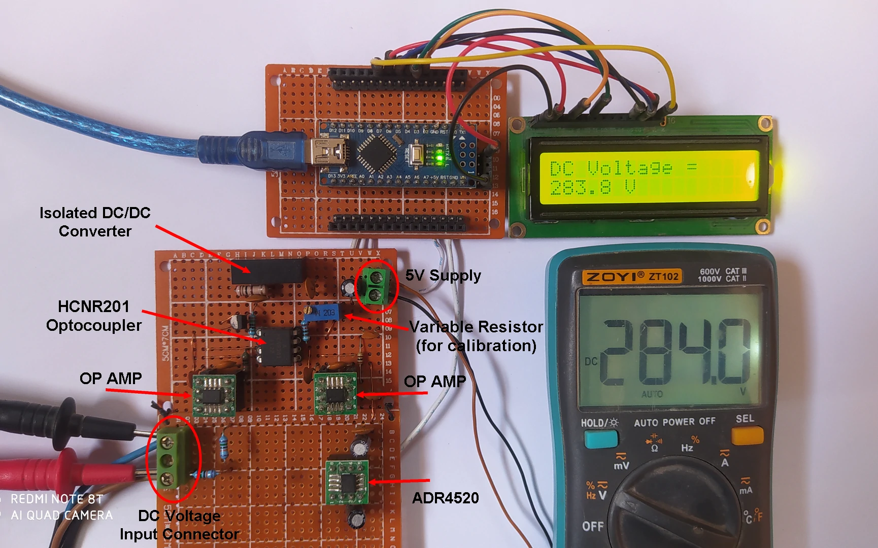
The image below shows my DIY hardware circuit of this project where components are clearly identified, wires between the DIY PCB and the Arduino board are soldered in the back of the two boards.
Isolated DC Voltage Measurement with Arduino and HCNR201 Optocoupler Video:
The following video shows my DIY circuit test, the displayed voltage values of the circuit are compared with the ones measured by a digital multimeter. My maximum test DC voltage was about 337V, I used a power rheostat to vary the input voltage between zero volt and its maximum value.
Discover more from Simple Circuit
Subscribe to get the latest posts sent to your email.


