Adding a serial-in parallel-out shift register such as the popular one 74HC595 to a 7-segment display will reduce number of pins required to drive it (the display).
Basically the 7-segment display requires 9 pins: 8 segment pins (A, B, C, D, E, F, G and DP) + common pin. By connecting all the segment pins to a shift register, the required number of pins becomes just 3: clock pin and data pin (for the shift register) + common pin.
So, for a 4-digit 7-segment display we need just 6 pins: clock, data and 4 common pins (each digit has its individual common pin).
This topic shows how to build a simple digital counter using PIC16F887 microcontroller, common anode 7-segment display with 4 digits and 74HC595 shift register.
The compiler used in this project is mikroC PRO for PIC.
To see how to interface PIC16F887 microcontroller with 7-segment display (without shift register) visit the following post:
Interfacing PIC microcontroller with 7-segment display | mikroC Projects
Hardware Required:
- PIC16F887 microcontroller —-> datasheet
- 4-Digit common anode 7-segment display
- 74HC595 shift register —-> datasheet
- 4 x PNP transistor (2SA1015, 2S9015, 2N3906 …)
- 8 x 100 ohm resistor
- 4 x 4.7k ohm resistor
- Push button
- 5V source
- Breadboard
- Jumper wires
7-Segment display with 74HC595 shift register circuit:
The image below shows our example circuit schematic diagram.
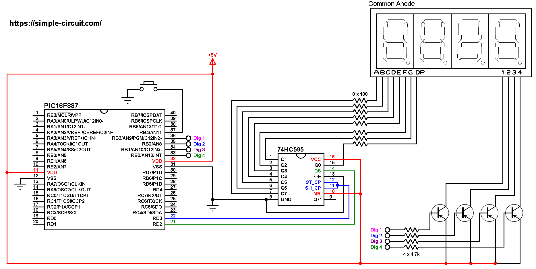
All the grounded terminals are connected together.
As shown in the circuit diagram above, all segment pins are connected to the 74HC595 output pins, each one through 100 ohm resistor, where:
Segment A … G are connected to 74HC595 pin Q7 … Q1 respectively and segment DP is connected to pin Q0.
The data pin of the 74HC595 shift register is named DS (#14) and it is connected to PIC16F887 pin RD2.
ST_CP (or RCLK) and SH_CP (or SRCLK) are connected together which then connected to PIC16F887 pin RD3, this is the clock pin.
Since the display has 4 digits, there’re 4 common pins: 1 (most left), 2, 3 and 4. Each common pin is connected to collector terminal of one transistor. Emitter terminals of the 4 transistors are connected to +5V. Base terminals of the four transistors are connected to the PIC16F887 through 4.7k resistors.
The 4 transistors are of the same type (PNP).
The push button which is connected to PIC16F887 pin RB4 is used to increment the displayed number.
The PIC16F887 microcontroller uses its internal oscillator @ 8 MHz, MCLR pin is configured as an input pin.
Project C code:
The following C code is for mikroC PRO for PIC compiler, it was tested with version 7.2.0.
Since the 4 digits are multiplexed we need to refresh the display very quickly (display one digit at a time, others are off), for that I used Timer0 module (8-bit timer) interrupt with 1:16 prescaler, this means Timer0 overflows every 2048 microseconds { 256/[8/(4 x 16)] = 256 x 8 = 2048 microseconds }.
Shift register clock pin and data pin are defined as:
1 2 3 | // shift register pins #define clockPin RD3_bit // clock pin #define dataPin RD2_bit // data pin |
Full mikroC code:
Configuration words:
CONFIG1 = 0x2CD4
CONFIG2 = 0x0700
1 2 3 4 5 6 7 8 9 10 11 12 13 14 15 16 17 18 19 20 21 22 23 24 25 26 27 28 29 30 31 32 33 34 35 36 37 38 39 40 41 42 43 44 45 46 47 48 49 50 51 52 53 54 55 56 57 58 59 60 61 62 63 64 65 66 67 68 69 70 71 72 73 74 75 76 77 78 79 80 81 82 83 84 85 86 87 88 89 90 91 92 93 94 95 96 97 98 99 100 101 102 103 104 105 106 107 108 109 110 111 112 113 114 115 116 117 118 119 120 121 122 123 124 125 126 127 128 | /************************************************************************************** 7-segment display with 74HC595 shift register. 4-Digit counter example. Common anode 7-segment display is used. C Code for mikroC PRO for PIC compiler. Internal oscillator used @ 8MHz Configuration words: CONFIG1 = 0x2CD4 CONFIG2 = 0x0700 This is a free software with NO WARRANTY. http://simple-circuit.com/ ***************************************************************************************/ // shift register pins #define clockPin RD3_bit // clock pin #define dataPin RD2_bit // data pin unsigned short current_digit; int count = 0; void datashift(unsigned short value_) { unsigned short i; for(i = 0x80; i; i >>= 1) { if (value_ & i) dataPin = 1; else dataPin = 0; clockPin = 1; clockPin = 0; } // send another clock pulse clockPin = 1; clockPin = 0; } void disp(unsigned short number) { switch (number) { case 0: // print 0 datashift(0x02); break; case 1: // print 1 datashift(0x9E); break; case 2: // print 2 datashift(0x24); break; case 3: // print 3 datashift(0x0C); break; case 4: // print 4 datashift(0x98); break; case 5: // print 5 datashift(0x48); break; case 6: // print 6 datashift(0x40); break; case 7: // print 7 datashift(0x1E); break; case 8: // print 8 datashift(0x00); break; case 9: // print 9 datashift(0x08); } } void interrupt() { PORTB = 0x0F; // turn off the display if(current_digit == 1){ disp(count / 1000); PORTB = 0x07; // turn on digit 1 (most left) } if(current_digit == 2){ disp((count / 100) % 10); PORTB = 0x0B; // turn on digit 2 } if(current_digit == 3){ disp((count / 10) % 10); PORTB = 0x0D; // turn on digit 3 } if(current_digit == 4){ disp(count % 10); PORTB = 0x0E; // turn on digit 4 (most right) } current_digit = (current_digit % 4) + 1; T0IF_bit = 0; // clear Timer0 interrupt flag bit } // main function void main() { OSCCON = 0x70; // set internal oscillator to 8MHz ANSELH = 0; // configure all PORTB pins as digital PORTB = 0; TRISB = 0xF0; // configure RB0, RB1, RB2 & RB3 as outputs PORTD = 0; TRISD = 0; TMR0 = 0; // reset Timer0 OPTION_REG = 0x03; // set Timer0 prescaler to 1:16 INTCON = 0xA0; // enable global interrupt & Timer0 overflow interrupt WPUB4_bit = 1; // enable RB4 internal weak pull-up while(1) { while(1) { if(PORTB.F4 ==0) { // if button is pressed count++; // increment 'count' by 1 if(count > 9999) count = 0; delay_ms(200); // wait 200 milliseconds } } } } // end of code. |
Project DIY hardware circuit is similar to the one shown in the video below where Arduino uno board is used instead of PIC16F887 microcontroller:
Discover more from Simple Circuit
Subscribe to get the latest posts sent to your email.


TO increase the current for driving 7-segment display and for multiplexing purpose
Can I ask what are the 4 PNP transistors needed.
i tried the circuit & the code but the circuit didnt work with me ,ive 2 issues 1st timing message 2nd instead of numbers it showed only 7segments lines
Make sure that you’re using common anode 7-segment display type!