The HC-SR04 ultrasonic sensor module can measure distances form 2 cm to 400 cm (4 m) with an accuracy of 3 mm. The HC-SR04 module includes ultrasonic transmitter, ultrasonic receiver and control circuit.
This post shows how to make a simple distance meter using PIC16F887 microcontroller and HC-SR04 ultrasonic sensor.
The compiler used in this project is Microchip MPLAB XC8 (MPLAB X IDE with MPLAB XC8 compiler).
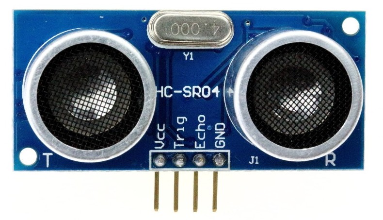
The HC-SR04 ultrasonic sensor module has 4 pins as shown in the image below where:
VCC : Positive power supply (+5V)
Trig : Trigger input pin
Echo : Echo output pin
GND : Ground (0V)
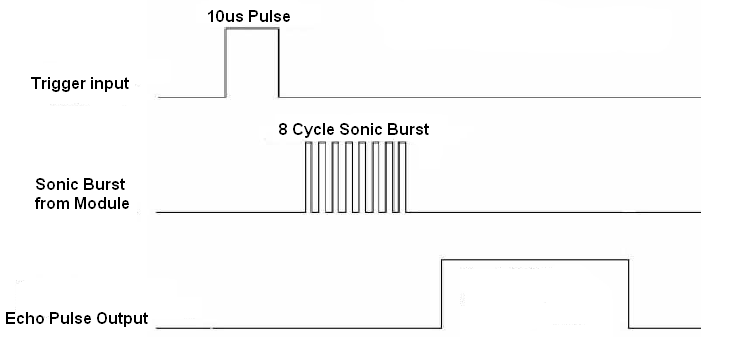
HC-SR04 ultrasonic sensor timing diagram:
The timing diagram of the HC-SR04 ultrasonic sensor is shown below.
First we have to supply the sensor trigger pin with a pulse of 10µs and the sensor will automatically send 8 cycles burst of ultrasound at 40 kHz and raise its echo pin. The Echo is a distance object that is pulse width and the range in proportion. We can calculate the range through the time interval between sending trigger signal and receiving echo signal. Formula: uS / 58 = centimeters or uS / 148 =inch; or:
the range = high level time x sound velocity / 2 where the sound velocity = 340M/S.
Related Projects:
To see how to interface PIC microcontroller with LCD module using MPLAB XC8 compiler, read the following post:
Interfacing LCD with PIC microcontroller | MPLAB Projects
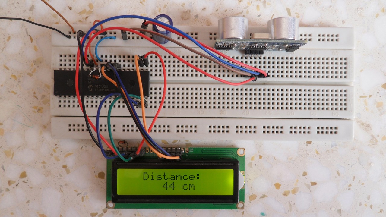
Hardware Required:
- PIC16F887 microcontroller —-> datasheet
- HC-SR04 ultrasonic sensor
- 16×2 LCD screen
- 10k ohm variable resistor or potentiometer
- 330 ohm resistor
- 5V source
- Breadboard
- Jumper Wires
Interfacing PIC microcontroller with HC-SR04 ultrasonic sensor circuit:
Distance meter project circuit schematic diagram is shown below.
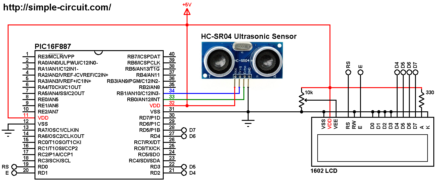
(All grounded terminals are connected together)
The HC-SR04 ultrasonic sensor board has 4 pins (from left to right): VCC (+5V), Trig (Trigger), Echo and GND (ground).
The Trigger pin is connected to pin RB1 (#34) and Echo pin is connected to pin RB0 (#33) of the PIC16F887 microcontroller.
The 16×2 LCD screen is connected to the PIC16F887 microcontroller as follows:
RS —> RD0 pin
E —> RD1 pin
D4 —> RD2 pin
D5 —> RD3 pin
D6 —> RD4 pin
D7 —> RD5 pin
VSS, RW, D0, D1, D2, D3 and K are connected to circuit GND (ground)
VEE to the variable resistor (or potentiometer) output pin
VDD to +5V and A to +5V through 330 ohm resistor
VEE pin is used to control the contrast of the LCD. A (anode) and K (cathode) are the back light LED pins.
In this project the PIC16F887 microcontroller runs with its internal oscillator @ 8 MHz, MCLR pin is configured as an input pin.
Interfacing PIC microcontroller with HC-SR04 ultrasonic sensor C code:
The C code below is for MPLAB XC8 compiler, it was tested with version 2.00 installed on MPLAB X IDE version 5.05.
To be able to compile the C code, a small LCD library for MPLAB XC8 compiler is required which can be downloaded from the following link:
MPLAB XC8 LCD Library
after the download, add the library file (LCD_Lib.c) to project folder.
In this project I used Timer1 module (16-bit timer) to measure signal widths (logic 1 and logic 0 widths), it is configured to increment every 1 us (1 tick per microsecond). That means Timer1 module clock frequency is 1MHz.
Functions used in the code:
__bit wait_sensor(): this function waits for sensor’s response, it returns 1 if there has been a response and 0 if time out. Here the time out is 1000 ticks = 1000 us = 1 ms.
__bit get_distance(uint16_t *ticks): this function measures the duration of the pulse sent by the HC-SR04 sensor (in microseconds). This duration is stored in the variable *ticks. This function returns 0 if OK and 1 if there is out of range or time out error. In this function Timer1 also is used to measure the pulse (high pulse) generated by the HC-SR04 sensor (Echo pulse).
Why 23200?
The actual distance (in cm) is equal to the width of the Echo pulse (in us) divided by 58. With the maximum distance that the sensor can measure is 400 cm we get a maximum Echo pulse (in us) of 400 x 58 = 23200
The connections between the microcontroller and the HC-SR04 sensor are defined as:
1 2 3 | // HC-SR Echo & Trigger pins are connected to RB0 & RB1 respectively #define ECHO_PIN RB0 #define TRIGGER_PIN RB1 |
The microcontroller used in this example is PIC16F887, configuration words are:
1 2 | #pragma config CONFIG1 = 0x2CD4 #pragma config CONFIG2 = 0x0700 |
Where:
- In-Circuit Debugger disabled
- Low voltage programming disabled
- Fail-Safe Clock Monitor enabled
- Internal/External Switchover mode enabled
- Brown-out Reset (BOR) disabled
- Data memory code protection disabled
- Program memory code protection disabled
- RE3/MCLR pin function is digital input, MCLR internally tied to VDD
- Power-up Timer (PWRT) disabled
- Watchdog Timer (WDT) disabled
- INTOSCIO oscillator: I/O function on RA6/OSC2/CLKOUT pin, I/O function on RA7/OSC1/CLKIN
- Flash Program Memory Self Write disabled
- Brown-out Reset set to 4.0V
Full MPLAB XC8 code:
1 2 3 4 5 6 7 8 9 10 11 12 13 14 15 16 17 18 19 20 21 22 23 24 25 26 27 28 29 30 31 32 33 34 35 36 37 38 39 40 41 42 43 44 45 46 47 48 49 50 51 52 53 54 55 56 57 58 59 60 61 62 63 64 65 66 67 68 69 70 71 72 73 74 75 76 77 78 79 80 81 82 83 84 85 86 87 88 89 90 91 92 93 94 95 96 97 98 99 100 101 102 103 104 105 106 107 108 109 110 111 112 113 114 115 116 117 118 119 120 121 122 123 124 125 126 127 128 129 130 131 132 | /* * Distance meter using HC-SR04 ultrasonic sensor and PIC16F887 MCU. * C Code for MPLAB XC8 compiler. * Internal oscillator used @ 8MHz. * This is a free software with NO WARRANTY. * http://simple-circuit.com/ */ // set configuration words #pragma config CONFIG1 = 0x2CD4 #pragma config CONFIG2 = 0x0700 // HC-SR Echo & Trigger pins are connected to RB0 & RB1 respectively #define ECHO_PIN RB0 #define TRIGGER_PIN RB1 //LCD module connections #define LCD_RS RD0 #define LCD_EN RD1 #define LCD_D4 RD2 #define LCD_D5 RD3 #define LCD_D6 RD4 #define LCD_D7 RD5 #define LCD_RS_DIR TRISD0 #define LCD_EN_DIR TRISD1 #define LCD_D4_DIR TRISD2 #define LCD_D5_DIR TRISD3 #define LCD_D6_DIR TRISD4 #define LCD_D7_DIR TRISD5 //End LCD module connections #include <xc.h> #define _XTAL_FREQ 8000000 #include <stdio.h> // for sprintf #include <stdint.h> // include stdint header #include "LCD_Lib.c" // include LCD driver source file char text[13]; __bit wait_sensor() { uint16_t i = 0; TMR1H = TMR1L = 0; // reset Timer1 TMR1ON = 1; // enable Timer1 module while(!ECHO_PIN && (i < 1000)) i = ( TMR1H << 8 ) | TMR1L; // read Timer1 and store its value in i if(i >= 1000) return 0; else return 1; } __bit get_distance(uint16_t *ticks) { *ticks = 0; TMR1H = TMR1L = 0; // reset Timer1 while( ECHO_PIN && (*ticks < 23200) ) *ticks = ( TMR1H << 8 ) | TMR1L; // read Timer1 value TMR1ON = 0; // disable Timer1 module if (*ticks >= 23200) return 1; else return 0; } /*************************** main function *********************/ void main(void) { OSCCON = 0x70; // set internal oscillator to 8MHz ANSELH = 0; // configure all PORTB pins as digital PORTB = 0; // PORTB output is zero TRISB1 = 0; // configure RB1 pin as input (HC-SR04 Echo pin) T1CON = 0x10; // set Timer1 clock source to internal with 1:2 prescaler (Timer1 clock = 1MHz) TMR1H = TMR1L = 0; // reset Timer1 __delay_ms(1000); // wait 1 second LCD_Begin(); // initialize LCD module LCD_Goto(4, 1); // move cursor to column 3, row 1 LCD_Print("Distance:"); while(1) { // send 10us pulse to HC-SR04 Trigger pin TRIGGER_PIN = 0; // make sure trigger pin is low __delay_us(2); // wait 2 us TRIGGER_PIN = 1; // now generate the 10 us pulse __delay_us(10); TRIGGER_PIN = 0; // read pulse comes from HC-SR04 Echo pin if (wait_sensor()) { // if there is a response from the sensor uint16_t distance; if(get_distance(&distance)) { // if distance > 400 cm LCD_Goto(3, 2); // move cursor to column 3 row 2 LCD_Print("Out of Range"); } else { distance = distance / 58; // calculate the actual distance in cm LCD_Goto(3, 2); // move cursor to column 6 row 2 sprintf(text, " %3u cm ", distance); LCD_Print(text); } } // end if (wait_sensor()) else { LCD_Goto(3, 2); // move cursor to column 3 row 2 LCD_Print(" Time Out "); } __delay_ms(200); // wait 200 ms } } /*************************** end main function ********************************/ |
The following video shows how a hardware circuit of the project should work (in the video PIC16F877A microcontroller is used):
Discover more from Simple Circuit
Subscribe to get the latest posts sent to your email.

Thanks simple-circuit!
please send hex file
Thanks sir ?