This project shows how to control a DC motor speed and direction of rotation using PIC16F887 microcontroller and L293D motor driver chip.
The L293D quadruple half-H drivers chip allows us to drive 2 motors in both directions. With one PWM signal from the PIC16F887 and two control signals we can easily control the speed as well as the direction of rotation of one DC motor. (PWM: Pulse Width Modulation).
The compiler used in this project is Microchip MPLAB XC8 (MPLAB X IDE with MPLAB XC8 compiler).
Components Required:
- PIC16F887 microcontroller —-> datasheet
- L293D driver —-> datasheet
- 12V DC motor
- 10k ohm potentiometer
- Push button
- 5V source
- 12V source
- Breadboard
- Jumper wires
DC Motor speed and direction control with PIC16F887 MCU and L293D circuit:
Project circuit schematic diagram is shown below.
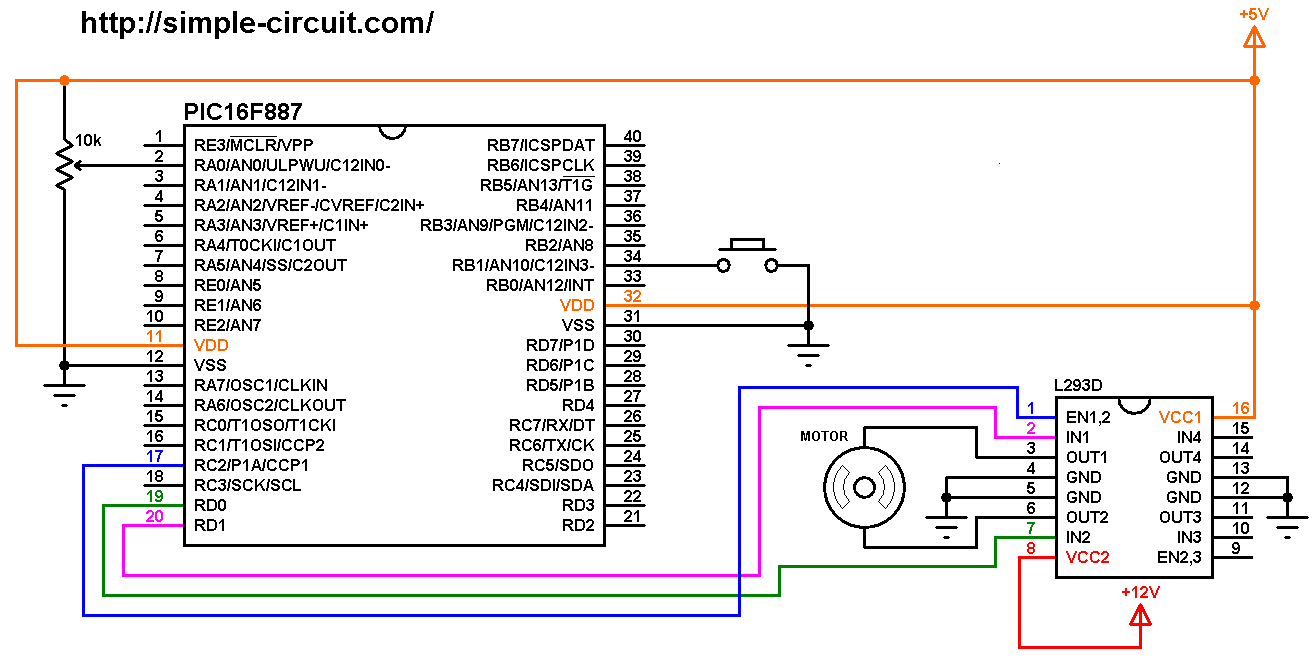
(All grounded terminals are connected together)
The circuit is supplied with two sources, one with voltage of 5V which supplies the PIC16F887 microcontroller and the L293D driver IC (VCC1), and the second source with voltage of 12V which supplies the L293D chip (VCC2) and therefore the DC motor. The DC motor nominal voltage is 12V.
The speed of the DC motor (both directions) is controlled with the 10k potentiometer which is connected to AN0 pin of the PIC16F887 (#2) and the direction of rotation is controlled with the push button which is connected to RB1 pin (#34). If the button is pressed the motor will change its direction of rotation directly.
The L293D driver has 2 VCCs: VCC1 is +5V and VCC2 is +12V (same as motor nominal voltage). IN1 and IN2 pins are the control pins where:
| IN1 | IN2 | Function |
| L | H | Direction 1 |
| H | L | Direction 2 |
| L | L | Fast motor stop |
| H | H | Fast motor stop |
The PIC16F887 generates a PWM signal on pin RC2 (#17) using CCP1 module (CCP: Capture/Compare/PWM), this pin is connected to EN1,2 pin of the L293D chip. IN1 and IN2 pins are connected to RD0 and RD1 respectively (they can be reversed).
In this project the PIC16F887 microcontroller uses its internal oscillator @ 8 MHz, MCLR pin is configured as an input pin.
DC Motor speed and direction control with PIC16F887 MCU and L293D code:
The C code below is for MPLAB XC8 compiler, it was tested with version 2.00 installed on MPLAB X IDE version 5.05.
PIC16F887 Timer2 module is configured to generate a PWM signal with frequency of 1.953 KHz and resolution of 10 bits (prescaler = 4 and preload value = 255).
PWM frequency and resolution can be calculated using the functions below (Fosc = 8 MHz):
PWM_freqency = Fosc / { [ (PR2) + 1 ] * 4 * ( TMR2 Prescaler Value ) } = 1.953 KHz
Resolution = log[ 4(PR2 + 1) ] / log(2) = 10 bits
1 2 3 4 | // Timer2 module configuration for PWM frequency of 1.953kHz & 10-bit resolution TMR2IF = 0; // clear Timer2 interrupt flag bit T2CON = 0x05; // enable Timer2 module with presacler = 4 PR2 = 0xFF; // Timer2 preload value = 255 |
Code functions:
uint16_t read_adc(): this function reads (and returns) data from ADC module registers ADRESH and ADRESL, the 2 registers contain digital value corresponds to analog voltage.
void set_pwm_duty(uint16_t pwm_duty): simply this function sets the PWM duty cycle.
__bit debounce (): this function is for button debounce.
The microcontroller used in this example is PIC16F887, configuration words are:
1 2 | #pragma config CONFIG1 = 0x2CD4 #pragma config CONFIG2 = 0x0700 |
Where:
- In-Circuit Debugger disabled
- Low voltage programming disabled
- Fail-Safe Clock Monitor enabled
- Internal/External Switchover mode enabled
- Brown-out Reset (BOR) disabled
- Data memory code protection disabled
- Program memory code protection disabled
- RE3/MCLR pin function is digital input, MCLR internally tied to VDD
- Power-up Timer (PWRT) disabled
- Watchdog Timer (WDT) disabled
- INTOSCIO oscillator: I/O function on RA6/OSC2/CLKOUT pin, I/O function on RA7/OSC1/CLKIN
- Flash Program Memory Self Write disabled
- Brown-out Reset set to 4.0V
Full MPLAB XC8 code:
1 2 3 4 5 6 7 8 9 10 11 12 13 14 15 16 17 18 19 20 21 22 23 24 25 26 27 28 29 30 31 32 33 34 35 36 37 38 39 40 41 42 43 44 45 46 47 48 49 50 51 52 53 54 55 56 57 58 59 60 61 62 63 64 65 66 67 68 69 70 71 72 73 74 75 76 77 78 79 80 81 82 83 84 85 86 87 88 89 90 91 92 93 94 95 96 97 98 99 100 101 102 103 104 105 106 107 108 109 110 111 112 113 114 | /* * DC Motor speed and direction of rotation control with PIC16F887 MCU. * C Code for MPLAB XC8 compiler. * Internal oscillator used @ 8MHz. * This is a free software with NO WARRANTY. * http://simple-circuit.com/ */ // set configuration words #pragma config CONFIG1 = 0x2CD4 #pragma config CONFIG2 = 0x0700 // direction button connected to pin RB1 #define Button RB1 // define motor control pins #define IN1 RD1 #define IN2 RD0 #include <xc.h> #define _XTAL_FREQ 8000000 #include <stdint.h> // include stdint header __bit direction = 0; // function for reading analog data uint16_t read_adc() { GO_nDONE = 1; // start an A/D conversion cycle while (GO_nDONE == 1) ; // wait for conversion complete return (ADRESH << 8) | ADRESL ; // return converted data } // set PWM1 duty cycle function void set_pwm_duty(uint16_t pwm_duty) { CCP1CON = ((pwm_duty << 4) & 0x30) | 0x0C; CCPR1L = pwm_duty >> 2; } // a small function for Button debounce __bit debounce () { uint8_t count = 0; for(uint8_t i = 0; i < 5; i++) { if (Button == 0) count++; __delay_ms(10); } if(count > 2) return 1; else return 0; } /*************************** main function *********************/ void main(void) { OSCCON = 0x70; // set internal oscillator to 8MHz ANSELH = 0; // configure all PORTB pins as digital PORTD = 0; // PORTD initial state TRISD = 0; // configure all PORTD pins as outputs // enable RB1 internal pull up nRBPU = 0; // clear RBPU bit (OPTION_REG.7) WPUB = 0x02; // WPUB register = 0b00000010 ADCON0 = 0xC1; // select channel 0 (AN0), // ADC clock derived from a dedicated internal oscillator, // enable ADC module ADCON1 = 0x80; // right justified, VSS & VDD references // PWM configuration RC2 = 0; // RC2 output low TRISC2 = 0; // configure RC2 pin as output (PWM signal output) CCP1CON = 0x0C; // configure CCP1 module as PWM with single output & clear duty cycle 2 LSBs CCPR1L = 0; // clear duty cycle 8 MSBs // Timer2 module configuration for PWM frequency of 1.953kHz & 10-bit resolution TMR2IF = 0; // clear Timer2 interrupt flag bit T2CON = 0x05; // enable Timer2 module with presacler = 4 PR2 = 0xFF; // Timer2 preload value = 255 __delay_ms(1000); // wait 1 second while(1) { if(!Button) // if Button is pressed if(debounce()) // call debounce function (make sure if Button is pressed) { direction = ~direction; // invert direction variable switch (direction) { case 0: IN1 = 1; IN2 = 0; break; case 1: IN1 = 0; IN2 = 1; } while(debounce()); // call debounce function (wait for Button to be released) } // read analog data and store it in 'motor_speed' uint16_t motor_speed = read_adc(); // set PWM duty cycle set_pwm_duty(motor_speed); __delay_ms(50); // wait 50 ms } } /*************************** end main function ********************************/ |
The following video shows a simple Proteus simulation of the project:
and this video shows how the project should work in hardware circuit where Arduino UNO board is used instead of the PIC16F887 microcontroller:
Discover more from Simple Circuit
Subscribe to get the latest posts sent to your email.

I am completely new to programming controllers, and have only just started learning to use MPLAB x. As a complete noobie, can you explain if the program above can be cut and paste directly in to the project, or does the configuration bits still need to set. If they do then could you please state what the actual settings are as I’m finding some of the settings difficult to find.