Interfacing the analog temperature sensor LM35 with PIC microcontroller is very easy, all what we need is an analog-to-digital converter (ADC) module associated with the PIC microcontroller. This page shows how to easily connect the LM35 sensor with PIC16F887 microcontroller and build a simple DIY thermometer. The compiler used in this project is mikroC PRO for PIC.
The LM35 temperature sensor is three pin device (VCC, OUT and GND) with an output voltage linearly related to Centigrade temperature (analog device). Since the LM35 output varies with dependent to the temperature we need an ADC (Analog-to-Digital Converter) module to measure this voltage. The ADC module converts analog data into digital data. The PIC16F887 microcontroller has 1 ADC module with 10-bit resolution and 14 channels.
The LM35 output has linear +10mV/°C scale factor means the following:
If the output voltage = 10mV —> temperature = 1°C
If the output voltage = 100mV —> temperature = 10°C
If the output voltage = 200mV —> temperature = 20°C
If the output voltage = 370mV —> temperature = 37°C
and so on.
Hardware Required:
- PIC16F887 microcontroller —> datasheet
- LM35 temperature sensor —> datasheet
- 1602 LCD screen
- 10k ohm variable resistor (or potentiometer)
- Breadboard
- 5V voltage source
- Jumper wires
- PIC Microcontroller programmer (PICkit 3, PICkit 4…)
Related Projects:
Interfacing PIC16F887 with LM35 temperature sensor – CCS C
LM335 Sensor interface with PIC16F887 MCU – mikroC Projects
Interfacing PIC microcontroller with LM35 sensor circuit:
Example circuit diagram is shown below.
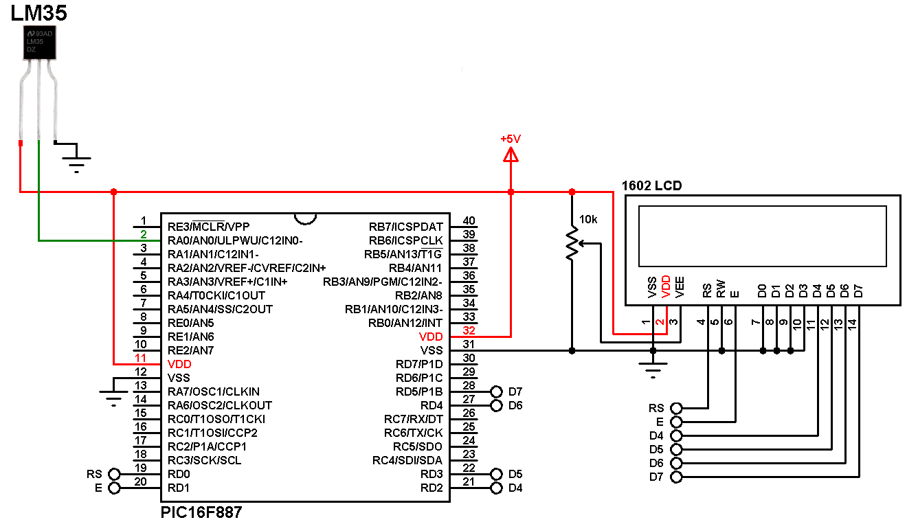
(All grounded terminals are connected together)
The LM35 has 3 pins (from left to right):
Pin 1: VCC, connected to +5V
Pin 2: analog output, connected to RA0/AN0
Pin 3: GND (ground), connected to the ground of the circuit (0V)
The output pin of the LM335 sensor is connected to RA0/AN0 pin (analog pin 0) of the PIC16F887.
The LCD module is connected to PORTD pins with:
RS —> RD0
E —> RD1
D4 —> RD2
D5 —> RD3
D6 —> RD4
D7 —> RD5
In this example the PIC16F887 microcontroller runs with its internal oscillator (@ 8MHz) and MCLR pin is configured as a digital input pin (configured in the software).
Interfacing PIC microcontroller with LM35 sensor mikroC code:
Reading voltage quantity using the ADC gives us a number between 0 and 1023 (10-bit resolution), 0V is represented by 0 and 5V is represented by 1023. Converting back the ADC digital value is easy and we can use the following equation for that conversion:
Voltage (in Volts) = ADC reading * 5 / 1023
Multiplying the previous result by 100 (LM35 scale factor is 10mV/°C = 0.01V/°C) will gives the actual temperature:
Temperature(°C) = ADC reading * 0.489
where 0.489 = 500 / 1023
mikroC configuration words are:
CONFIG1 : 0x2CD4
CONFIG2 : 0x0700
The configuration words can be changed from: Project –> Edit Project … and change the parameters.
Full mikroC code:
1 2 3 4 5 6 7 8 9 10 11 12 13 14 15 16 17 18 19 20 21 22 23 24 25 26 27 28 29 30 31 32 33 34 35 36 37 38 39 40 41 42 43 44 45 46 47 48 49 50 51 52 | // Interfacing LM35 sensor with PIC16F887 mikroC code // Internal oscillator used @ 8MHz // Configuration words: CONFIG1 = 0x2CD4 // CONFIG2 = 0x0700 // LCD module connections sbit LCD_RS at RD0_bit; sbit LCD_EN at RD1_bit; sbit LCD_D4 at RD2_bit; sbit LCD_D5 at RD3_bit; sbit LCD_D6 at RD4_bit; sbit LCD_D7 at RD5_bit; sbit LCD_RS_Direction at TRISD0_bit; sbit LCD_EN_Direction at TRISD1_bit; sbit LCD_D4_Direction at TRISD2_bit; sbit LCD_D5_Direction at TRISD3_bit; sbit LCD_D6_Direction at TRISD4_bit; sbit LCD_D7_Direction at TRISD5_bit; // End LCD module connections char Temperature[] = " 00.0 C"; unsigned int Temp; void main() { OSCCON = 0X70; // Set internal oscillator to 8MHz ANSEL = 1; // Configure RA0 pin as analog (AN0) Lcd_Init(); // Initialize LCD module Lcd_Cmd(_LCD_CURSOR_OFF); // cursor off Lcd_Cmd(_LCD_CLEAR); // clear LCD lcd_out(1, 3, "Temperature:"); while(1) { Temp = ADC_Read(0) * 0.489; // Read analog voltage and convert it to degree Celsius (0.489 = 500/1023) if (temp > 99) Temperature[0] = 1 + 48; // Put 1 (of hundred) else Temperature[0] = ' '; // Put space Temperature[1] = (temp / 10) % 10 + 48; Temperature[2] = temp % 10 + 48; Temperature[5] = 223; // Put degree symbol ( ° ) lcd_out(2, 5, Temperature); // Display LM35 temperature result delay_ms(1000); // Wait 1 second } } // End of code |
Proteus simulation of the project should give the same result as shown in the video below where CCS C compiler is used instead of mikroC PRO for PIC:
Discover more from Simple Circuit
Subscribe to get the latest posts sent to your email.


