This small post shows how to start using PIC12F1822 DAC (Digital-to Analog Converter) module.
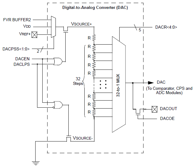
PIC12F1822 microcontroller has 1 DAC module. The DAC can be used to supply analog voltage on RA0 pin with 32 selectable output levels.
The input of the DAC can be connected to:
- External VREF pins
- VDD supply voltage
- FVR (Fixed Voltage Reference)
DAC Block diagram is shown below:
With CCS PIC C compiler we can initialize the DAC module using the following command:
setup_dac(int8 mode);
Where mode can one of the following modes:
DAC_OFF 0 // DAC disabled
DAC_VSS_VDD // Negative source is VSS and positive source is VDD
DAC_VSS_VREF // Negative source is VSS and positive source is Vref+ pin
DAC_VSS_FVR // Negative source is VSS and positive source is FVR (Fixed Voltage Reference)
The DAC output can be enabled using the following line which or’ed with above in setup_dac() using |.
DAC_OUTPUT // Enable ADC output on RA0 pin.
Controlling the output of the DAC is also easy with CCS PIC C compiler and for that we have to use the following command:
dac_write(int8 value);
Where value should be a 5-bit number which varies between 0 and 31.
The DAC output voltage is determined by the following equation assuming that the DAC is enabled (DACEN bit is 1):
Assume that we’ve PIC12F1822 microcontroller with +5V power supply, the DAC is configured with VSS and VDD as negative and positive sources and the DAC output is enabled.
Minimum Vout voltage when DACR[4 : 0] = 0b00000 equals to 0V.
Maximum Vout voltage when DACR[4 : 0] = 0b11111 equals to 4.84V
Writing DACR[4 : 0] = 0b00000 is done using: dac_write(0);
And DACR[4 : 0] = 0b11111 is dac_write(31);
PIC12F1822 DAC Module Example:
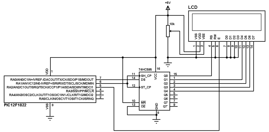
This is a small example for the DAC module. Example circuit schematic is shown below.

PIC12F1822 internal oscillator is used.
A potentiometer is used to control the DAC output.
A voltmeter is connected between pin RA0 which is the DAC output (DACOUT) and the ground to see the variation of the voltage according to the potentiometer position.
PIC12F1822 DAC Module Example CCS C Code:
1 2 3 4 5 6 7 8 9 10 11 12 13 14 15 16 17 18 19 20 21 22 23 | /* PIC12F1822 DAC Module Example CCS C code DAC output (DACOUT) on RA0 pin */ #include <12F1822.h> #fuses NOMCLR INTRC_IO PLL_SW #device ADC = 8 // 8-bit ADC resolution #use delay(clock=32000000) unsigned int16 i=0; void main() { setup_oscillator(OSC_8MHZ | OSC_PLL_ON); // Set internal oscillator to 8MHz with PLL enabled (32MHz) setup_adc(ADC_CLOCK_DIV_32); // Set ADC conversion time to 32Tosc setup_adc_ports(sAN1); // Configure AN1 pin as analog set_adc_channel(1); // Select channel AN1 setup_dac(DAC_VSS_VDD | DAC_OUTPUT); // Negative source is VSS and positive source is VDD with output enabled while(TRUE){ i = read_adc(); // Read analog value from AN1 and store in i i = (i * 31)/255; dac_write(i); // Write DAC value according to i delay_ms(10); } } |
PIC12F1822 DAC module example Proteus simulation video:
The following video shows simulation of our example with Proteus.
Discover more from Simple Circuit
Subscribe to get the latest posts sent to your email.

Please write this DAC code in mikroC compiler.
Hi! I think that in your code the DAC should be set as DAC_VSS_VDD
Great Post!!!
Corrected, thanks.