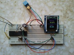
This post shows how to interface PIC16F877A microcontroller with DHT11 relative humidity and temperature sensor and 1.8″ ST7735R SPI TFT display.
DHT11 sensor is a digital device used to sense relative humidity and temperature and convert that data into digital signals. For more details about this type of sensors and how to interface it with PIC16F877A microcontroller see the following two topics:
Interfacing PIC16F877A with DHT11 (RHT01) sensor Proteus simulation
Interfacing DHT11 relative humidity and temperature sensor with PIC16F877A
And to see how to interface PIC16F877A with ST7735 SPI TFT display read the following topic:
ST7735 1.8″ TFT display with PIC16F877A example
Components List:
- PIC16F877A Microcontroller
- ST7735R SPI TFT Display
- DHT11 (RHT01) Sensor
- 8MHz Crystal oscillator
- 2 x 22pF Capacitors
- 10K Resistor
- 4.7K Resistor
- 5 x 1K Resistors
- +5V Power Supply Source
- Breadboard
- Jumper Wires
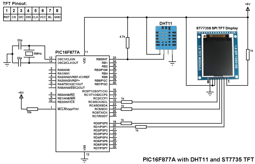
PIC16F877A With DHT11 sensor and ST7735 SPI TFT circuit:
PIC16F877A With DHT11 sensor and ST7735 SPI TFT CCS C code:
PIC16F877A hardware SPI module is used in this project..
ST7735 SPI TFT driver is required to compile this code, download link in this topic:
ST7735 SPI TFT Display Driver for CCS PIC C compiler
The code is has been tested with versions 4.068 and 5.051.
1 2 3 4 5 6 7 8 9 10 11 12 13 14 15 16 17 18 19 20 21 22 23 24 25 26 27 28 29 30 31 32 33 34 35 36 37 38 39 40 41 42 43 44 45 46 47 48 49 50 51 52 53 54 55 56 57 58 59 60 61 62 63 64 65 66 67 68 69 70 71 72 73 74 75 76 77 78 79 80 81 82 83 84 85 86 87 88 89 90 91 92 93 94 95 96 97 98 99 100 101 102 103 104 105 106 107 108 109 110 111 112 113 114 115 116 117 118 119 120 121 122 123 124 125 126 127 128 129 130 131 132 133 134 135 136 137 138 139 140 141 142 143 144 | /* PIC16F877A with DHT11 sensor and ST7735 1.8" SPI color TFT display example CCS C code ST7735 TFT display driver for CCS PIC C compiler is required */ // TFT module connections #define TFT_CS PIN_D1 #define TFT_DC PIN_D0 #define TFT_SPI_HARDWARE // End TFT module connections #include <16F877A.h> #fuses HS,NOWDT,NOPROTECT,NOLVP #use delay(clock = 8000000) #include <ST7735_TFT.c> #use fast_io(D) #use fast_io(B) #define DHT11_PIN PIN_B0 // DHT11 Data pin is connected to pin RB0 char *text = "DHT11 Sensor with PIC16F877A and ST7735 TFT"; char temperature[] = "00.0"; char humidity[] = "00.0%"; short Time_out; unsigned int8 T_byte1, T_byte2, RH_byte1, RH_byte2, CheckSum, clear = 0 ; void start_signal(){ output_drive(DHT11_PIN); // Configure DHT11 pin as output output_low(DHT11_PIN); // DHT11 pin output low delay_ms(25); output_high(DHT11_PIN); // DHT11 pin output high delay_us(30); output_float(DHT11_PIN); // Configure v pin as input } short check_response(){ delay_us(40); if(!input(DHT11_PIN)){ // Read and test if DHT11 pin is low delay_us(80); if(input(DHT11_PIN)){ // Read and test if DHT11 pin is high delay_us(50); return 1; } } } unsigned int8 Read_Data(){ unsigned int8 i, k, _data = 0; // k is used to count 1 bit reading duration if(Time_out) break; for(i = 0; i < 8; i++){ k = 0; while(!input(DHT11_PIN)){ // Wait until DHT11 pin get raised k++; if(k > 100){ Time_out = 1; break; } delay_us(1); } delay_us(30); if(!input(DHT11_PIN)) bit_clear(_data, (7 - i)); // Clear bit (7 - i) else{ bit_set(_data, (7 - i)); // Set bit (7 - i) while(input(DHT11_PIN)){ // Wait until DHT11 pin goes low k++; if(k > 100){ Time_out = 1; break; } delay_us(1);} } } return _data; } void main(){ TFT_BlackTab_Initialize(); fillScreen(ST7735_BLACK); drawtext(0, 0, text, ST7735_WHITE, ST7735_BLACK, 1); drawFastHLine(0, 35, _width, ST7735_BLUE); while(TRUE){ Time_out = 0; Start_signal(); if(check_response()){ // If there is a response from sensor RH_byte1 = Read_Data(); // read RH byte1 RH_byte2 = Read_Data(); // read RH byte2 T_byte1 = Read_Data(); // read T byte1 T_byte2 = Read_Data(); // read T byte2 Checksum = Read_Data(); // read checksum if(Time_out){ // If reading takes long time if(clear != 1){ clear = 1; fillrect(0, 40, _width, 120, ST7735_BLACK); } strcpy(text, "Time out!"); drawtext(10, 90, text, ST7735_RED, ST7735_BLACK, 2); } else{ if(CheckSum == ((RH_Byte1 + RH_Byte2 + T_Byte1 + T_Byte2) & 0xFF)){ temperature[0] = T_Byte1/10 + 48; temperature[1] = T_Byte1%10 + 48; temperature[3] = T_Byte2/10 + 48; humidity[0] = RH_Byte1/10 + 48; humidity[1] = RH_Byte1%10 + 48; humidity[3] = RH_Byte2/10 + 48; if(clear != 2){ clear = 2; fillrect(0, 50, _width, 120, ST7735_BLACK); drawFastHLine(0, 96, _width, ST7735_BLUE); } strcpy(text, "Temperature:"); drawtext(28, 50, text, ST7735_MAGENTA, ST7735_BLACK, 1); drawtext(34, 70, temperature, ST7735_YELLOW, ST7735_BLACK, 2); drawCircle(84, 70, 2, ST7735_YELLOW); drawchar(90, 70, 'C', ST7735_YELLOW, ST7735_BLACK, 2); strcpy(text, "Humidity:"); drawtext(37, 110, text, ST7735_MAGENTA, ST7735_BLACK, 1); drawtext(34, 130, humidity, ST7735_CYAN, ST7735_BLACK, 2); } else{ if(clear != 3){ clear = 3; fillrect(0, 40, _width, 120, ST7735_BLACK); } strcpy(text, "Checksum"); drawtext(16, 80, text, ST7735_RED, ST7735_BLACK, 2); strcpy(text, "Error!"); drawtext(28, 100, text, ST7735_RED, ST7735_BLACK, 2); } } } else { if(clear != 4){ clear = 4; fillrect(0, 40, _width, 120, ST7735_BLACK); } strcpy(text, "No"); drawtext(52, 60, text, ST7735_RED, ST7735_BLACK, 2); strcpy(text, "response"); drawtext(16, 80, text, ST7735_RED, ST7735_BLACK, 2); strcpy(text, "from the"); drawtext(16, 100, text, ST7735_RED, ST7735_BLACK, 2); strcpy(text, "sensor"); drawtext(28, 120, text, ST7735_RED, ST7735_BLACK, 2); } delay_ms(1000); } } |
PIC16F877A With DHT11 sensor and ST7735 SPI TFT video:
This video shows a simple hardware circuit of this project.
Discover more from Simple Circuit
Subscribe to get the latest posts sent to your email.

Sorry i forgot to say that pic877a and pic 876a communicate to each other with spi protocoll.
#define SPI_MODE_0 (SPI_L_TO_H | SPI_XMIT_L_TO_H)
#define SPI_MODE_1 (SPI_L_TO_H)
#define SPI_MODE_2 (SPI_H_TO_L)
#define SPI_MODE_3 (SPI_H_TO_L | SPI_XMIT_L_TO_H)
setup_spi(SPI_MASTER | SPI_MODE_0 | SPI_CLK_DIV_16);
setup_spi(SPI_SLAVE | SPI_MODE_0);
According to ST7735 color TFT driver do i have to change from SPI_CLK_DIV_16 to SPI_CLK_DIV_4
and SPI_MODE from 0 to 3?
i mean in my system i use for mster’s program the following command
setup_spi(SPI_MASTER | SPI_L_TO_H | SPI_XMIT_L_TO_0 | SPI_CLK_DIV_16);
and for the slave’s program i use this command
setup_spi(SPI_SLAVE | SPI_L_TO_H | SPI_XMIT_L_TO_H);
If i want to add the ST7735 color TFT intomy system do i have to change these commnds?
I have made an automation home system which a pic16f877a works as a master that collect data and send them to a pic16876a(works as a slave) that excecute commands. Now i want to put temperature sensors on each room, but i dont want to use 16×2/ 20×4 LCD screen (with HD44780 controller) because of too many cables. Is it possible to add a ST7735 TFT as a slave?
Yes of course, instead of the 20×4 or 16×2 LCD you could use other ones such as the ST7735 color TFT or SSD1306 OLED monochrome display which uses I2C protocol (2 lines only + reset line between the MCU and the display).
in this project coud we add another slave device..Is it possible?
Which device (example)?