With the help of L239D we can easily control DC motor speed and direction of rotation.
The L293D can control two motors with the same nominal voltage independently and in this project we are going to use half of the chip to control just one motor.
The microcontroller used in this project is PIC12F1822, it’s an 8-bit and 8 pins microcontroller. This microcontroller has 1 CCP module which can be used to generate a PWM signal.
The following topic shows how to use PIC12F1822 ADC and PWM modules:
PIC12F1822 ADC and PWM modules
DC Motor control using PIC12F1822 and L293D circuit:
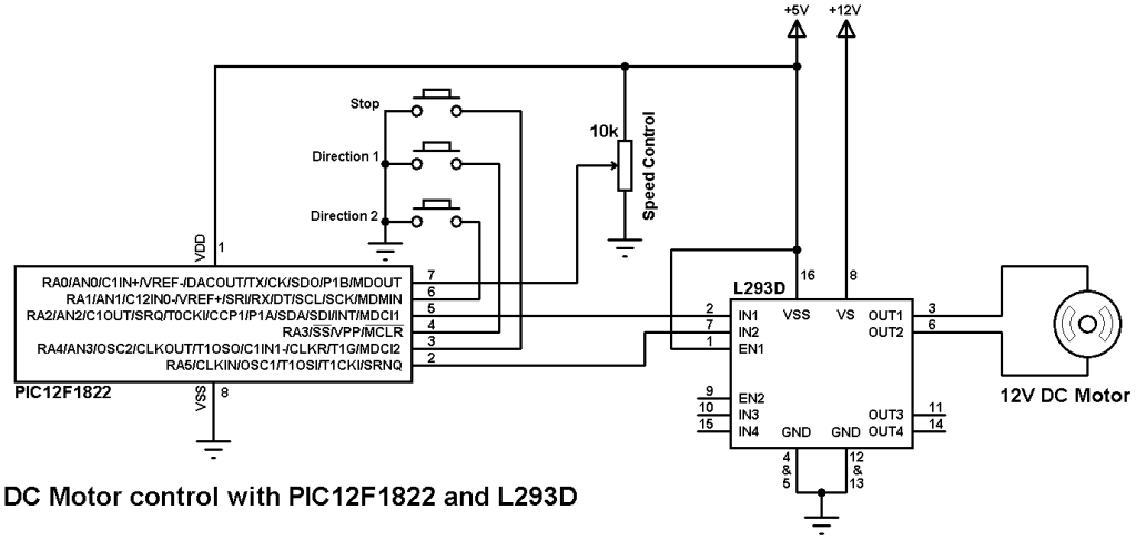
Motor speed is controlled from a 10k potentiometer connected to RA0 pin. Two push buttons connected to RA1 and RA3 are used to select direction of rotation and another push button connected to RA4 is used to stop the motor.
The DC motor voltage is 12V which is the same as L293D VS voltage (pin 8).
The PWM signal output pin is selected by the software (RA2 or RA5).
PIC12F1822 internal oscillator is used and internal pull-ups is enabled for the inputs.
Here the microcontroller reads the analog data comes from the potentiometer and uses the corresponding digital value to set the PWM duty cycle.
DC Motor control using PIC12F1822 and L293D CCS C code:
In this project PIC12F1822 internal oscillator is used @ 8MHz with PLL enabled (gives 32MHz) and internal pull-ups are enebled for the inputs RA1, RA3 and RA4.
Timer2 is configured to generate a PWM signal of 1.95KHz with a resolution of 10-bit.
setup_timer_2(T2_DIV_BY_16, 255, 1);
CCP Module is configured to work as PWM module and the output pin of the PWM signal can be selected using the following two lines:
setup_ccp1(CCP_PWM | CCP1_A2);
setup_ccp1(CCP_PWM | CCP1_A5);
The complete CCS C code is below.
1 2 3 4 5 6 7 8 9 10 11 12 13 14 15 16 17 18 19 20 21 22 23 24 25 26 27 28 29 30 31 32 33 34 35 36 37 38 39 40 41 42 43 44 45 46 47 | // DC Motor control using PIC12F1822 and L293D CCS C code #include <12F1822.h> #fuses NOMCLR INTRC_IO PLL_SW #device ADC = 10 #use delay(clock=32000000) #use fast_io(A) int8 s; // Used to know motor status int16 i; void main() { setup_oscillator(OSC_8MHZ | OSC_PLL_ON); // Set internal oscillator to 32MHz (8MHz and PLL) output_a(0); set_tris_a(0x1B); // Configure RA0, RA1, RA3 & RA4 as inputs port_a_pullups(0x1A); // Enable internal pull-ups for pins RA1, RA3 & RA4 setup_adc(ADC_CLOCK_DIV_32); // Set ADC conversion time to 32Tosc setup_adc_ports(sAN0); // Configure AN0 pin as analog set_adc_channel(0); // Select analog channel AN0 setup_ccp1(CCP_OFF); // CCP1 OFF setup_timer_2(T2_DIV_BY_16, 255, 1); // Set PWM frequency to 1.95KHz with 10-bit resolution while(TRUE){ if(s != 0){ i = read_adc(); // Read from AN0 and store in i set_pwm1_duty(i); // Set pwm1 duty cycle delay_ms(10); // Wait 10 ms } if(!input(PIN_A1) && (s != 1)){ // If RA1 button pressed s = 1; setup_ccp1(CCP_OFF); // CCP1 OFF output_a(0); delay_ms(50); setup_ccp1(CCP_PWM | CCP1_A2); // Configure CCP1 as a PWM (output at RA2) } if(!input(PIN_A3) && (s != 2)){ // If RA3 button pressed s = 2; setup_ccp1(CCP_OFF); // CCP1 OFF output_a(0); delay_ms(50); setup_ccp1(CCP_PWM | CCP1_A5); // Configure CCP1 as a PWM (output at RA5) } if(!input(PIN_A4) && (s != 0)){ // If RA4 button pressed s = 0; setup_ccp1(CCP_OFF); // CCP1 OFF output_a(0); } } } |
Discover more from Simple Circuit
Subscribe to get the latest posts sent to your email.