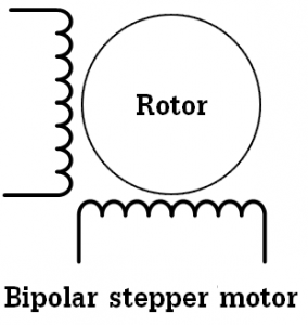
Most of cd-rom or dvd-rom drives has a bipolar stepper motor, this motor has two windings and each winding has 2 inputs which means that this type of motor has 4 wires.
This topic shows circuit schematic and C code for controlling the bipolar stepper motor speed and direction using PIC16F877A microcontroller.
The stepper motor can be controlled in full step mode or half step mode. The full step mode is a little bit easier than the half step control mode. In this topic the full step control mode is used.
To control the bipolar stepper motor we need two H-bridge circuits and for that L293D motor driver chip is used, this cheap chip can work as a dual H-bridge drivers.
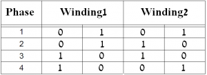
In the full step control mode always both windings are energized according to the following two tables where table1 shows the driving sequence for rotation direction 1:

And the following table shows driving sequence for the other rotation direction:
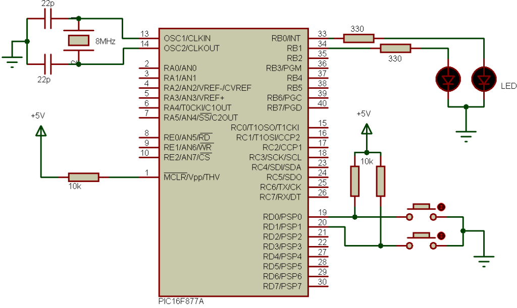
Interfacing PIC16F877A with bipolar stepper motor circuit:
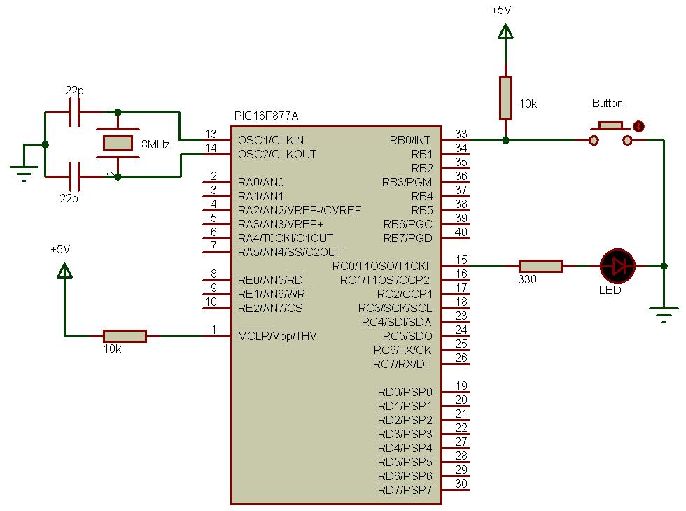
The following image shows circuit schematic diagram of this project where two pushbuttons are used to choose motor rotation direction and a potentiometer to control motor speed. PortB internal pull-ups are enabled in the C code.

The PIC16F877A needs +5V supply on its VDD and VSS pins.
Interfacing PIC16F877A with bipolar stepper motor CCS C code:
A pot connected to AN0 is used to control the speed of the stepper motor. The microcontroller reads the analog data from AN0 and uses the digital value to change the delay between motor driving phases and when the delay increases the motor speed decreases and vise versa.
The two pushbuttons which are connected to RB0 and RB1 are used to choose motor rotation direction and when RB0 button pressed the driving sequence follows the first table above and when RB1 button is pressed the driving sequence follows the second table.
8-bit ADC resolution is used.
1 2 3 4 5 6 7 8 9 10 11 12 13 14 15 16 17 18 19 20 21 22 23 24 25 26 27 28 29 30 31 32 33 34 35 36 37 38 39 40 41 42 43 44 45 46 47 48 49 50 51 52 53 54 55 | // Interfacing PIC16F877A with cd-rom bipolar stepper motor #include <16F877A.h> #fuses HS,NOWDT,NOPROTECT,NOLVP #use delay(clock = 8000000) #use fast_io(B) #use fast_io(D) unsigned int8 speed_; void stepper_move(short direction_){ if(direction_){ output_d(0b00000110); delay_ms(speed_); output_d(0b00000101); delay_ms(speed_); output_d(0b00001001); delay_ms(speed_); output_d(0b00001010); delay_ms(speed_); } else{ output_d(0b00000101); delay_ms(speed_); output_d(0b00000110); delay_ms(speed_); output_d(0b00001010); delay_ms(speed_); output_d(0b00001001); delay_ms(speed_); } } void main(){ output_b(0); set_tris_b(0x03); port_b_pullups(TRUE); output_d(0); set_tris_d(0); setup_adc(ADC_CLOCK_DIV_32); // Set ADC conversion time to 32Tosc setup_adc_ports(AN0); // Configure AN0 as analog set_adc_channel(0); // Select channel 0 input delay_ms(100); // Wait 100ms while(TRUE){ output_d(0); while(!input(PIN_B0)){ speed_ = read_adc(); if(speed_ < 2) speed_ = 2; stepper_move(0); } while(!input(PIN_B1)){ speed_ = read_adc(); if(speed_ < 2) speed_ = 2; stepper_move(1); } } } |
Interfacing PIC16F877A with bipolar stepper motor video:
The following video shows the project in hardware circuit.
Discover more from Simple Circuit
Subscribe to get the latest posts sent to your email.

Thank you for the informative video, can I get help to have delayed for around 7 mins for stepper motor to rotate.