This example shows how to use a rotary encoder with PIC16F877A microcontroller in order to control the speed and direction of rotation of a DC motor.
Previously I posted an example shows how to control a DC motor speed and direction using PIC16F877A and a potentiometer, example link is below:
DC motor control with PIC16F877A and L293D – Proteus simulation
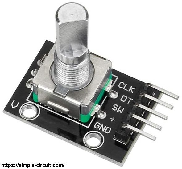
In this example I used the rotary encoder shown in the image below:
The rotary encoder has 5 pins: GND, + (+5V or 3.3V), SW (push button), DT (pin B) and CLK (pin A).
As an addition to the rotary encoder there is a push button and three pull up resistors for pins SW, DT and CLK of 10K ohm. With the three pull-up resistors, the normal state of each terminal is logic high.
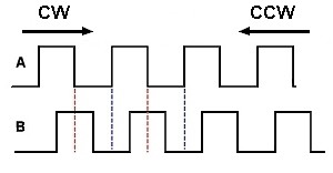
The rotary encoder generates (when rotating) two square waves on pins A (CLK) and B (DT) with 90° out of phase as shown in the figure below:
As shown in the figure, the rotary encoder has 4 phases:
phase 1: A = 0, B = 0
phase 2: A = 1, B = 0
phase 3: A = 1, B = 1
phase 4: A = 0, B = 1
Hardware Required:
- PIC16F877A microcontroller —> datasheet
- Rotary encoder
- DC motor
- L293D motor driver
- 20MHz crystal oscillator
- 2 x 22pF ceramic capacitors
- 10k ohm resistor
- Breadboard
- 12V source
- 5V source
- Jumper wires
DC Motor speed and direction control using PIC16F877A and rotary encoder circuit:
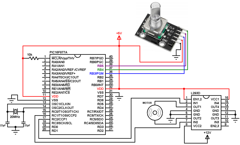
Example circuit schematic diagram is shown below.
All grounded terminals are connected.
The L293D quadruple half-H drivers chip allows us to drive 2 motors in both directions. With two PWM outputs from the PIC16F877A microcontroller we can easily control the speed as well as the direction of rotation of one DC motor. (PWM: Pulse Width Modulation).
The L293D is supplied with 2 different sources, the first one (VCC1) is +5V, and the 2nd one (VCC2) is +12V which is the same as motor nominal voltage. Pin IN1 and pin IN2 are the control pins where:
| IN1 | IN2 | Function |
| L | H | Direction 1 |
| H | L | Direction 2 |
| L | L | Fast motor stop |
| H | H | Fast motor stop |
The PIC16F877A microcontroller has two CCP modules, CCP1 and CCP2 (CCP: Capture/Compare/PWM). By setting both modules in PWM mode we get 2 PWM signals with the same frequency on pins RC2 (PWM1) and RC1 (PWM2), at any time there is only 1 active PWM, this allows us to control the direction as well as the speed by varying the duty cycle of the active PWM signal. The active PWM pin decides the motor direction of rotation (one at a time, the other output is logic 0).
The rotary encoder push button terminal is connected to pin RB3, with this button we can change the direction of rotation of the motor. CLK and DT pins are connected to RB4 and RB5 respectively.
The Code:
The C code below is for CCS C compiler!
PORTB interrupt on change (IOC) is used to detect the movement of the rotary encoder.
1 2 3 4 5 6 7 8 9 10 11 12 13 14 15 16 17 18 19 20 21 22 23 24 25 26 27 28 29 30 31 32 33 34 35 36 37 38 39 40 41 42 43 44 45 46 47 48 49 50 51 52 53 54 55 56 57 58 59 60 61 62 63 64 65 66 67 68 69 70 71 72 73 74 75 | // DC motor control with PIC16F877A and rotary encoder CCS C code. #define SW PIN_B3 // Rotary encoder button pin connection #include <16F877A.h> #fuses HS,NOWDT,NOPROTECT,NOLVP #use delay(clock = 20MHz) #use fast_io(B) int1 motor_direction; int8 last_read; signed int8 quad = 0, change; signed int16 motor_speed = 0; #INT_RB // RB port interrupt on change void RB_IOC_ISR(void) { int8 encoderRead; clear_interrupt(INT_RB); encoderRead = input_b() & 0x30; if(encoderRead == last_read) return; if(bit_test(encoderRead, 4) == bit_test(last_read, 5)) quad -= 1; else quad += 1; last_read = encoderRead; } signed int8 EncoderGet(void) { signed int8 value = 0; while(quad >= 4){ value += 1; quad -= 4; } while(quad <= -4){ value -= 1; quad += 4; } return value; } void main() { port_b_pullups(TRUE); enable_interrupts(GLOBAL); clear_interrupt(INT_RB); setup_timer_2(T2_DIV_BY_16, 63, 1); // Set PWM frequency to 4.88 KHz with 8-bit resolution delay_ms(1000); last_read = input_b() & 0x30; enable_interrupts(INT_RB); while(TRUE) { delay_ms(50); change = EncoderGet(); if(change){ motor_speed += change; if(motor_speed > 255) motor_speed = 255; if(motor_speed < 0) motor_speed = 0; set_pwm1_duty(motor_speed); // Set pwm1 duty cycle set_pwm2_duty(motor_speed); // Set pwm2 duty cycle } if(!input(SW)) { while(!input(SW)); motor_direction = !motor_direction; if(motor_direction) { setup_ccp2(CCP_OFF); output_low(PIN_C1); setup_ccp1(CCP_PWM); } else { setup_ccp1(CCP_OFF); output_low(PIN_C2); setup_ccp2(CCP_PWM); } } } } |
The video below shows how this example works:
Reference:
CCS C compiler rotary encoder example (ex_sk_rotary_encoder_isr.c)
Discover more from Simple Circuit
Subscribe to get the latest posts sent to your email.

Thanks a lot my dear friend.
I have solded my rotary prob
lems in my head with your writing.