After I successfully interfaced the PIC16F887 microcontroller with ST7735R (ST7735S) SPI color TFT module, now let’s see how to build a real time clock with temperature monitor using PIC16F887 MCU, ST7735R TFT and DS3231 RTC module. The compiler used in this project is mikroC PRO for PIC.
Related Project:
Interfacing PIC microcontroller with ST7735R SPI TFT – mikroC Projects
Hardware Required:
- PIC16F887 microcontroller —> datasheet
- DS3231 board —> DS3231 datasheet
- ST7735R (ST7735S) TFT screen
- 20 MHz crystal oscillator
- 2 x 22 pF ceramic capacitor
- 5 x 1K ohm resistor
- 2 x push button
- 3V coin cell battery
- Power source with 5V
- Breadboard
- Jumper wires
- PIC programmer (PICkit 2, PICkit 3…)
Real time clock with temperature monitor and color display circuit:
Project circuit schematic diagram is shown below.
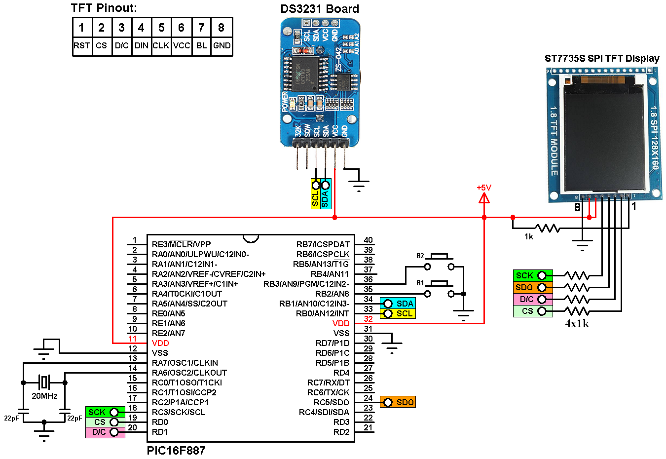
(All grounded terminals are connected together)
In the circuit there are 2 pushbuttons (B1 & B2) connected to pins RB2 and RB3 of the PIC16F887 microcontroller respectively, the two push buttons are used to set time and date parameters (minutes, hours, day of the week, date, month and year). Button B1 selects the parameter and B2 increments the selected parameter.
In this project PORTB pull-ups are enabled (in the software) for pins RB2 and RB3 which means there is no need for external pull up resistors. Also, there is no pull-up resistor connected to MCLR pin because it is configured to work as a digital input pin (in the software).
SCL and SDA lines of the DS3231 are connected to RB0 and RB1 pins of the PIC16F887 respectively.
In this project I used 20MHz crystal oscillator which is the maximum speed of the PIC16F887, this gives the highest SPI data transfer rate (5Mbit/s). Lower crystal frequencies can be used or even the internal oscillator of the microcontroller.
Real time clock with temperature monitor and color display C code:
To be able to compile the mikroC code below we need a small file named ST7735_TFT.c , this file is the driver (library) of this type of TFT. The library file download link can be found at the end of this topic:
ST7735R SPI TFT driver for mikroC PRO for PIC
After downloading the driver file just put it in the project folder.
Since the PIC16F887 has one MSSP module (Master Synchronous Serial Port module) which can operate in SPI mode or I2C mode, also they share the same pins, I used software I2C to communicate between the master device (the microcontroller) and the slave device (DS3231).
mikroC PRO for PIC compiler has a nice library for software I2C, SCL and SDA connections can be configured as:
// Software I2C connections (needed for DS3231 RTC)
sbit Soft_I2C_SCL at RB0_bit;
sbit Soft_I2C_SDA at RB1_bit;
sbit Soft_I2C_SCL_Direction at TRISB0_bit;
sbit Soft_I2C_SDA_Direction at TRISB1_bit;
// End Software I2C connections
and it can be initialize with the function: Soft_I2C_Init() .
The software I2C library has a fixed clock frequency of 20KHz, the DS3231 can work with this speed.
I used PIC16F887 MSSP module in SPI mode for faster data transfer between the microcontroller and the ST7735S TFT display. Software SPI can be used but its very slow compared to hardware SPI.
Configuration words:
CONFIG1: 0x2CD2
CONFIG2: 0x0700
Full mikroC code:
1 2 3 4 5 6 7 8 9 10 11 12 13 14 15 16 17 18 19 20 21 22 23 24 25 26 27 28 29 30 31 32 33 34 35 36 37 38 39 40 41 42 43 44 45 46 47 48 49 50 51 52 53 54 55 56 57 58 59 60 61 62 63 64 65 66 67 68 69 70 71 72 73 74 75 76 77 78 79 80 81 82 83 84 85 86 87 88 89 90 91 92 93 94 95 96 97 98 99 100 101 102 103 104 105 106 107 108 109 110 111 112 113 114 115 116 117 118 119 120 121 122 123 124 125 126 127 128 129 130 131 132 133 134 135 136 137 138 139 140 141 142 143 144 145 146 147 148 149 150 151 152 153 154 155 156 157 158 159 160 161 162 163 164 165 166 167 168 169 170 171 172 173 174 175 176 177 178 179 180 181 182 183 184 185 186 187 188 189 190 191 192 193 194 195 196 197 198 199 200 201 202 203 204 205 206 207 208 209 210 211 212 213 214 215 216 217 218 219 220 221 222 223 224 225 226 227 228 229 230 231 232 233 234 235 236 | /* Real Time clock with temperature monitor and color TFT using PIC16F887 microcontroller and ST7735R 128x160 TFT module C Code for mikroC PRO for PIC compiler ST7735R driver source file must be added to the project folder! High speed oscillator used @ 20MHz Configuration words: CONFIG1 = 0x2CD2 CONFIG2 = 0x0700 */ #define button1 PORTB.F2 // Button B1 is connected to RB2 pin #define button2 PORTB.F3 // Button B2 is connected to RB3 pin // Software I2C connections (needed for DS3231 RTC) sbit Soft_I2C_SCL at RB0_bit; sbit Soft_I2C_SDA at RB1_bit; sbit Soft_I2C_SCL_Direction at TRISB0_bit; sbit Soft_I2C_SDA_Direction at TRISB1_bit; // End Software I2C connections // SPI TFT module connections #define TFT_SPI_HARDWARE // Hardware SPI module is used sbit TFT_CS at RD0_bit; // TFT CS pin is connected to RD0 pin sbit TFT_DC at RD1_bit; // TFT DC pin is connected to RD1 pin sbit TFT_CS_Direction at TRISD0_bit; sbit TFT_DC_Direction at TRISD1_bit; // End SPI TFT module connections #include <ST7735_TFT.c> // Include ST7735 TFT driver source file char Time[] = " : : "; char Calendar[] = " / /20 "; char temperature[] = " 00.00"; short temperature_msb; unsigned short i, second, minute, hour, day, date, month, year, temperature_lsb; void display_day(){ switch(day){ case 1: drawtext(40, 10, " SUNDAY ", ST7735_CYAN, ST7735_BLACK, 1); break; case 2: drawtext(40, 10, " MONDAY ", ST7735_CYAN, ST7735_BLACK, 1); break; case 3: drawtext(40, 10, " TUESDAY ", ST7735_CYAN, ST7735_BLACK, 1); break; case 4: drawtext(40, 10, "WEDNESDAY", ST7735_CYAN, ST7735_BLACK, 1); break; case 5: drawtext(40, 10, "THURSDAY ", ST7735_CYAN, ST7735_BLACK, 1); break; case 6: drawtext(40, 10, " FRIDAY ", ST7735_CYAN, ST7735_BLACK, 1); break; default: drawtext(40, 10, "SATURDAY ", ST7735_CYAN, ST7735_BLACK, 1); } } void DS3231_display(){ // Convert BCD to decimal second = (second >> 4) * 10 + (second & 0x0F); minute = (minute >> 4) * 10 + (minute & 0x0F); hour = (hour >> 4) * 10 + (hour & 0x0F); date = (date >> 4) * 10 + (date & 0x0F); month = (month >> 4) * 10 + (month & 0x0F); year = (year >> 4) * 10 + (year & 0x0F); // End conversion Time[7] = second % 10 + 48; Time[6] = second / 10 + 48; Time[4] = minute % 10 + 48; Time[3] = minute / 10 + 48; Time[1] = hour % 10 + 48; Time[0] = hour / 10 + 48; Calendar[9] = year % 10 + 48; Calendar[8] = year / 10 + 48; Calendar[4] = month % 10 + 48; Calendar[3] = month / 10 + 48; Calendar[1] = date % 10 + 48; Calendar[0] = date / 10 + 48; if(temperature_msb < 0){ temperature_msb = abs(temperature_msb); temperature[0] = '-'; } else temperature[0] = ' '; temperature_lsb >>= 6; temperature[2] = temperature_msb % 10 + 48; temperature[1] = temperature_msb / 10 + 48; if(temperature_lsb == 0 || temperature_lsb == 2){ temperature[5] = '0'; if(temperature_lsb == 0) temperature[4] = '0'; else temperature[4] = '5'; } if(temperature_lsb == 1 || temperature_lsb == 3){ temperature[5] = '5'; if(temperature_lsb == 1) temperature[4] = '2'; else temperature[4] = '7'; } drawtext(4, 27, Calendar, ST7735_YELLOW, ST7735_BLACK, 2); drawtext(16, 81, Time, ST7735_GREEN, ST7735_BLACK, 2); drawtext(14, 134, temperature, ST7735_WHITE, ST7735_BLACK, 2); drawCircle(90, 134, 2, ST7735_WHITE); // Print degree symbol (°) drawtext(96, 134, "C", ST7735_WHITE, ST7735_BLACK, 2); } void blink_parameter(){ short j = 0; while(j < 10 && button1 && button2){ j++; delay_ms(25); } } unsigned short edit(unsigned short x_pos, unsigned short y_pos, unsigned short parameter){ char *text = " "; unsigned int color = ST7735_YELLOW; text[0] = (parameter / 10) + 48; text[1] = (parameter % 10) + 48; if(i == 3 || i == 4) color = ST7735_GREEN; while(!button1); // Wait until button B1 released while(1){ while(!button2){ // If button (pin #9) is pressed parameter++; if(i == 0 && parameter > 31) // If date > 31 ==> date = 1 parameter = 1; if(i == 1 && parameter > 12) // If month > 12 ==> month = 1 parameter = 1; if(i == 2 && parameter > 99) // If year > 99 ==> year = 0 parameter = 0; if(i == 3 && parameter > 23) // If hours > 23 ==> hours = 0 parameter = 0; if(i == 4 && parameter > 59) // If minutes > 59 ==> minutes = 0 parameter = 0; text[0] = (parameter / 10) + 48; text[1] = (parameter % 10) + 48; drawtext(x_pos, y_pos, text, color, ST7735_BLACK, 2); delay_ms(200); // Wait 200ms } fillRect(x_pos, y_pos, 22, 16, ST7735_BLACK); blink_parameter(); drawtext(x_pos, y_pos, text, color, ST7735_BLACK, 2); blink_parameter(); if(!button1){ // If button (pin #8) is pressed i++; // Increament 'i' for the next parameter return parameter; // Return parameter value and exit } } } void main() { ANSELH = 0; // Configure all PORTB pins as digital OPTION_REG.F7 = 0; // Enable PORTB internal pull-ups WPUB = 0x0C; // Enable RB2 & RB3 internal pull-ups Soft_I2C_Init(); // Initialize Soft I2C communication ST7735_TFT_Init(); // Initialize the TFT module fillScreen(ST7735_BLACK); // Fill the screen with black color // Draw fast two blue horizontal lines drawFastHLine(0, 53, TFT_Width, ST7735_BLUE); drawFastHLine(0, 106, TFT_Width, ST7735_BLUE); // Draw two texts ("TIME" and "TEMPERATURE") drawtext(52, 64, "TIME", ST7735_MAGENTA, ST7735_BLACK, 1); drawtext(30, 117, "TEMPERATURE", ST7735_RED, ST7735_BLACK, 1); while(1) { if(!button1){ // If button B1 is pressed i = 0; while(!button1); // Wait for button B1 release while(1){ while(!button2){ // While button B2 pressed day++; // Increment day if(day > 7) day = 1; display_day(); // Call display_day function delay_ms(200); // Wait 200 ms } fillRect(40, 10, 54, 8, ST7735_BLACK); // Draw rectangle (erase day from the display) blink_parameter(); // Call blink_parameter function display_day(); // Call display_day function blink_parameter(); // Call blink_parameter function if(!button1) // If button B1 is pressed break; } date = edit(4, 27, date); // Edit date month = edit(40, 27, month); // Edit month year = edit(100, 27, year); // Edit year hour = edit(16, 81, hour); // Edit hours minute = edit(52, 81, minute); // Edit minutes // Convert decimal to BCD minute = ((minute / 10) << 4) + (minute % 10); hour = ((hour / 10) << 4) + (hour % 10); date = ((date / 10) << 4) + (date % 10); month = ((month / 10) << 4) + (month % 10); year = ((year / 10) << 4) + (year % 10); // End conversion // Write data to DS3231 RTC Soft_I2C_Start(); // Start I2C protocol Soft_I2C_Write(0xD0); // DS3231 address Soft_I2C_Write(0); // Send register address (seconds) Soft_I2C_Write(0); // Reset sesonds and start oscillator Soft_I2C_Write(minute); // Write minute value to DS3231 Soft_I2C_Write(hour); // Write hour value to DS3231 Soft_I2C_Write(day); // Write day value (not used) Soft_I2C_Write(date); // Write date value to DS3231 Soft_I2C_Write(month); // Write month value to DS3231 Soft_I2C_Write(year); // Write year value to DS3231 Soft_I2C_Stop(); // Stop I2C protocol delay_ms(200); // Wait 200ms } // Read time and date Soft_I2C_Start(); // Start I2C protocol Soft_I2C_Write(0xD0); // DS3231 address Soft_I2C_Write(0); // Send register address (seconds) Soft_I2C_Start(); // Restart I2C Soft_I2C_Write(0xD1); // Initialize data read second = Soft_I2C_Read(1); // Read seconds from register 0 minute = Soft_I2C_Read(1); // Read minuts from register 1 hour = Soft_I2C_Read(1); // Read hour from register 2 day = Soft_I2C_Read(1); // Read day from register 3 date = Soft_I2C_Read(1); // Read date from register 4 month = Soft_I2C_Read(1); // Read month from register 5 year = Soft_I2C_Read(0); // Read year from register 6 Soft_I2C_Stop(); // Stop I2C protocol // Read temperature Soft_I2C_Start(); // Start I2C protocol Soft_I2C_Write(0xD0); // DS3231 address Soft_I2C_Write(0x11); // Send register address (temperature MSB) Soft_I2C_Start(); // Restart I2C Soft_I2C_Write(0xD1); // Initialize data read temperature_msb = Soft_I2C_Read(1); // Read temperature MSB temperature_lsb = Soft_I2C_Read(0); // Read temperature LSB Soft_I2C_Stop(); // Stop I2C protocol display_day(); // Display day DS3231_display(); // Diaplay time & date delay_ms(50); // Wait 50ms } } // End of code |
The result of this project should be the same as the one shown in the two videos below where PIC16F877A is used with CCS C compiler.
The first video shows a simple hardware circuit of the project:
and the second video shows the simulation of the project with Proteus:
PIC16F887 + DS3231 RTC + ST7735S TFT Proteus simulation file download:
Download
Discover more from Simple Circuit
Subscribe to get the latest posts sent to your email.


