This article shows how to get started with PIC18F4550 microcontroller USART module using CCS PIC C compiler.
PIC18F4550 microcontroller has one (1) USART (Universal Synchronous/Asynchronous Receive/Transmit) module. This module can work in USRT mode or UART mode. In this topic we are going to use the USART module as UART (Universal Asynchronous Receive/Transmit) to transmit and receive data between the microcontroller and the computer.
PIC18F4550 UART connection circuit schematic:
Pin RC6 (TX) and pin RC7 (RX) are used for the UART (serial) communication between the microcontroller and the computer. To change between TTL logic levels (5V) and RS232 signals (+/-12V), an IC is needed which is max232.
Don’t connect TX and RX pins directly to an RS232 serial port which may damage your microcontroller.
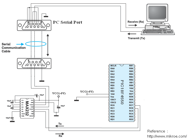
In this example the PIC18F4550 microcontroller uses its internal oscillator and MCLR pin function is disabled.
PIC18F4550 UART example CCS C code:
This is the full C code of this example.
1 2 3 4 5 6 7 8 9 10 11 12 13 14 15 16 17 18 19 20 21 22 23 24 25 26 27 28 29 30 31 | // CCS C UART example for PIC18F4550 microcontroller #include <18F4550.h> #fuses NOMCLR INTRC_IO #use delay(clock = 8000000) #use rs232(uart1, baud = 9600) // Initialize UART module #include char message[] = "PIC18F4550 microcontroller UART example" ; char i, j, textsize; void main(){ setup_oscillator(OSC_8MHZ); // Set internal oscillator to 8MHz putc(13); // Go to first column printf("Hello world!"); // UART write delay_ms(5000); // Wait 5 seconds putc(13); // Go to first column putc(10); // Start a new line textsize = strlen(message); // Number of characters in message for(j = 0; j < textsize; j++){ putc(message[j]); delay_ms(100); } putc(13); // Go to first column putc(10); // Start a new line while(TRUE){ if(kbhit()){ // If data has been received i = getc(); // UART read putc(i); // Send it back } } } |
PIC18F4550 UART example video:
The following video shows communication between the computer and PIC18F4550 using UART module.
