After I build NEC remote control decoder using Microchip PIC16F887 8-bit microcontroller and MikroElektronika mikroC PRO for PICcompiler, now let’s see how to decode IR remote controls which use RC-5 communication protocol. NEC decoder project link is below:
NEC remote control decoder with PIC16F887 and mikroC compiler
Also I made the same project which I’m going to do but using CCS PIC C compiler, project link is below with some information about the RC5 protocol:
RC-5 Decoder with PIC16F887 microcontroller and CCS C compiler
Components Required:
- PIC16F887 microcontroller —> datasheet
- IR Receiver
- 1602 LCD screen
- 10K ohm variable resistor
- 5V Power source
- Protoboard
- Jumper wires
The Circuit:
RC-5 decoder with PIC16F887 circuit diagram is shown below.
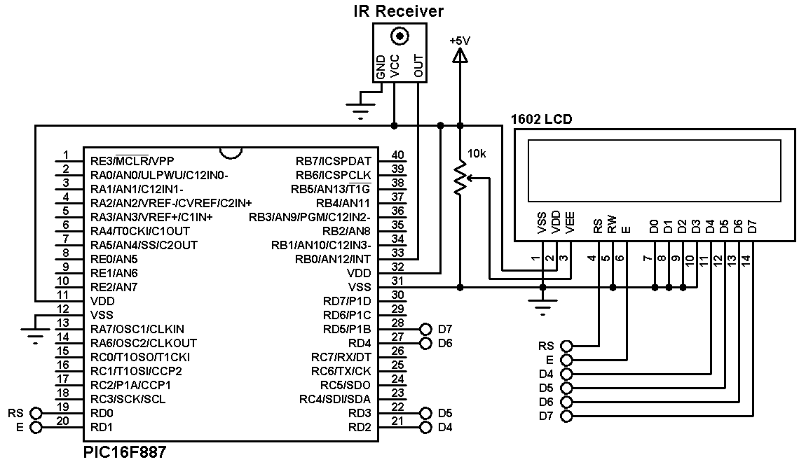
In this example the PIC16F887 microcontroller runs with its internal oscillator and MCLR pin is configured as digital input (configured in the software).
The IR receiver has three pins: VCC, OUT and GND. The output is connected to pin RB0.
The 1602 LCD screen (2 rows and 16 columns) is used to display the RMS value of the applied voltage, it is connected to the PIC18F46K22 MCU as follows:
RS —> pin RD0
E —> pin RD1
D4 —> pin RD2
D5 —> pin RD3
D6 —> pin RD4
D7 —> pin RD5
VSS, RW, D0, D1, D2, D3, and K are connected to circuit ground
VEE to the variable resistor (or potentiometer) output
VDD to +5V and A to +5V through 330 ohm resistor.
VEE pin is used to control the contrast of the LCD. A (anode) and K (cathode) are the back light LED pins.
RC-5 decoder mikroC code:
Before writing the C code of the decoder, I drew a simple state machine of the RC5 protocol which helped me a lot in the code. The state machine is shown below.
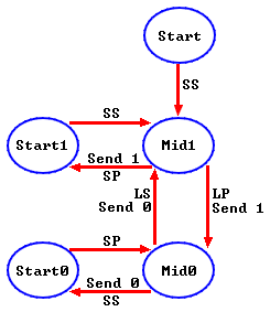
Where:
SP : Short Pulse (About 889µs)
LP : Long Pulse (About 1778µs)
SS: Short Space (About 889µs)
LS : Long Space (About 1778µs)
The resolution of the code is good as we’re working with interrupts.
Rest of code description is below.
1 2 3 4 5 6 7 8 9 10 11 12 13 14 15 16 17 18 19 20 21 22 23 24 25 26 27 28 29 30 31 32 33 34 35 36 37 38 39 40 41 42 43 44 45 46 47 48 49 50 51 52 53 54 55 56 57 58 59 60 61 62 63 64 65 66 67 68 69 70 71 72 73 74 75 76 77 78 79 80 81 82 83 84 85 86 87 88 89 90 91 92 93 94 95 96 97 98 99 100 101 102 103 104 105 106 107 108 109 110 111 112 113 114 115 116 117 118 119 120 121 122 123 124 125 126 127 128 129 130 131 132 133 134 135 136 137 138 139 140 141 142 143 144 145 146 147 148 149 150 151 152 153 154 155 156 157 158 159 160 161 162 163 164 165 166 167 | //////////////////////////////////////////////////////////////////////////////////////////////// // // // RC5 Remote control decoder mikroC PRO for PIC compiler code // // Used MCU: PIC16F887 runs with internal oscillator @ 8MHz // // // // The message of the RC5 protocol is 14-bit long, 2 start bits (always 1), toggle bit, // // address (5 bits) and command (6 bits). // // The length of 1 bit is 1778µs which can be divided into two parts of 889µs. A logic 1 // // is represented by 889µs low and 889µs high. A logic zero is represented by 889µs high // // and 889µs low. // // The RC5 protocol has 4 states: start1, mid1, start0 and mid0. // // The IR receiver output is logic high at idle state and when it receives a // // burst it changes the output to logic low. // // The output of the IR receiver is connected to interrupt pin RB0 (interrupt on change) // // and every change in the pin status generates an interrupt and Timer1 starts calculating, // // Timer1 value will be used in the next interrupt, this means Timer1 calculates the time // // between two interrupts which is pulse time or space time. // // Timer1 time step is 1µs (Timer1 increments every 1µs). If you use mcu frequency other // // than 8MHz, make sure to keep Timer1 time step to 1µs, otherwise time intervals (short_ // // time, med_time and long_time) have to be changed. // // Also, Timer1 interrupt is used for time out (very long pulse or very long space). This // // interrupt resets the decoding process. // // The decoding results are displayed on 1602 LCD screen connected to PORTD. // // // //////////////////////////////////////////////////////////////////////////////////////////////// // LCD module connections sbit LCD_RS at RD0_bit; sbit LCD_EN at RD1_bit; sbit LCD_D4 at RD2_bit; sbit LCD_D5 at RD3_bit; sbit LCD_D6 at RD4_bit; sbit LCD_D7 at RD5_bit; sbit LCD_RS_Direction at TRISD0_bit; sbit LCD_EN_Direction at TRISD1_bit; sbit LCD_D4_Direction at TRISD2_bit; sbit LCD_D5_Direction at TRISD3_bit; sbit LCD_D6_Direction at TRISD4_bit; sbit LCD_D7_Direction at TRISD5_bit; // End LCD module connections #define short_time 700 // Used as a minimum time for short pulse or short space #define med_time 1200 // Used as a maximum time for short pulse or short space #define long_time 2000 // Used as a maximum time for long pulse or long space char text[3]; bit rc5_ok, toggle_bit; unsigned short rc5_state, address, command, i; unsigned int rc5_code, timer_value; void Interrupt() { if (RBIF_bit && (PORTB.F0 || !PORTB.F0)){ // PORTB change ISR RBIF_bit = 0; if(rc5_state != 0){ timer_value = (TMR1H << 8) + TMR1L; // Store Timer1 value TMR1H = 0; // Reset Timer1 TMR1L = 0; } switch(rc5_state){ case 0 : // Start receiving IR data (initially we're at the beginning of mid1) TMR1H = 0; // Reset Timer1 TMR1L = 0; TMR1ON_bit = 1; // Enable Timer1 rc5_state = 1; // Next state: end of mid1 i = 0; break; case 1 : // End of mid1 ==> check if we're at the beginning of start1 or mid0 if((timer_value > long_time) || (timer_value < short_time)){ // Invalid interval ==> stop decoding and reset rc5_state = 0; // Reset decoding process TMR1ON_bit = 0; // Disable Timer1 break; } rc5_code |= 1 << (13 - i); // Set bit (13 - i) i++; if(i > 13){ // If all bits are received rc5_ok = 1; // Decoding process is OK RBIE_bit = 0; // Disable PORTB change interrupt break; } if(timer_value > med_time){ // We're at the beginning of mid0 rc5_state = 2; // Next state: end of mid0 if(i == 13){ // If we're at the LSB bit rc5_ok = 1; // Decoding process is OK rc5_code &= ~1; // Clear the LSB bit RBIE_bit = 0; // Disable PORTB change interrupt break; } } else // We're at the beginning of start1 rc5_state = 3; // Next state: end of start1 break; case 2 : // End of mid0 ==> check if we're at the beginning of start0 or mid1 if((timer_value > long_time) || (timer_value < short_time)){ rc5_state = 0; // Reset decoding process TMR1ON_bit = 0; // Disable Timer1 break; } rc5_code &= ~(1 << (13 - i)); // Clear (13 - i) i++; if(timer_value > med_time) // We're at the beginning of mid1 rc5_state = 1; // Next state: end of mid1 else // We're at the beginning of start0 rc5_state = 4; // Next state: end of start0 break; case 3 : // End of start1 ==> check if we're at the beginning of mid1 if((timer_value > med_time) || (timer_value < short_time)){ // Time interval invalid ==> stop decoding TMR1ON_bit = 0; // Disable Timer1 rc5_state = 0; // Reset decoding process break; } else // We're at the beginning of mid1 rc5_state = 1; // Next state: end of mid1 break; case 4 : // End of start0 ==> check if we're at the beginning of mid0 if((timer_value > med_time) || (timer_value < short_time)){ // Time interval invalid ==> stop decoding TMR1ON_bit = 0; // Disable Timer1 rc5_state = 0; // Reset decoding process break; } else // We're at the beginning of mid0 rc5_state = 2; // Next state: end of mid0 if(i == 13){ // If we're at the LSB bit rc5_ok = 1; // Decoding process is OK rc5_code &= ~1; // Clear the LSB bit RBIE_bit = 0; // Disable PORTB change interrupt } } } if (TMR1IF_bit){ // Timer1 ISR TMR1IF_bit = 0; // Clear Timer1 overflow flag bit rc5_state = 0; // Reset decoding process TMR1ON_bit = 0; // Disable Timer1 } } void main() { OSCCON = 0X70; // Set internal oscillator to 8MHz rc5_ok = 0; rc5_state = 0; ANSELH = 0; // Configure all PORTB pins as digital Lcd_Init(); // Initialize LCD module Lcd_Cmd(_LCD_CURSOR_OFF); // cursor off Lcd_Cmd(_LCD_CLEAR); // clear LCD TMR1IF_bit = 0; // Clear Timer1 overflow interrupt flag bit RBIF_bit = 0; // Clear PORTB change interrupt flag bit TMR1IE_bit = 1; // Enable Timer1 overflow interrupt T1CON = 0x10; // Set Timer1 clock source to internal with 1:2 prescaler (Timer1 clock = 1MHz) INTCON = 0xC8; // Enable global, peripheral and PORTB change interrupts IOCB0_bit = 1; // Enable RB0 pin change interrupt Lcd_Out(1, 1, "ADS:0x00 TGL: 0"); Lcd_Out(2, 1, "CMD:0x00"); while(1) { while(!rc5_ok); // Wait until RC5 code receiver rc5_ok = 0; // Reset decoding process rc5_state = 0; TMR1ON_bit = 0; // Disable Timer1 toggle_bit = rc5_code >> 11; // Toggle bit is bit number 11 address = (rc5_code >> 6) & 0x1F; // Next 5 bits are for address command = rc5_code & 0x3F; // The 6 LSBits are command bits Lcd_Chr(1, 16, toggle_bit + 48); // Display toggle bit ByteToHex(address, text); // Save address in string text with hex format Lcd_Out(1, 7, text); // Display address ByteToHex(command, text); // Save command in string text with hex format Lcd_Out(2, 7, text); // Display command RBIE_bit = 1; // Enable PORTB change interrupt } } |
The video below shows a simple hardware circuit of the decoder:
Discover more from Simple Circuit
Subscribe to get the latest posts sent to your email.


