This tutorial shows how to use rotary encoder with STM32 Blue Pill board where the position of the rotary encoder is printed on a 4-digit seven-segment display module based on TM1637 driver.
The STM32 Blue Pill development board is based on STMicroelectronics ARM Cortex-M3 microcontroller STM32F103C8T6 running at maximum clock frequency of 72MHz. This particular development board gained popularity due to its low cost and compact size, making it a popular choice for hobbyists, students, and developers.
To use the STM32 Blue Pill, a hardware programmer, such as the ST-Link, is required to upload the code to the board. A USB-to-Serial converter module can also be used to upload the code to the board, one example of this converter is the popular one from FTDI which is FT232RL module.
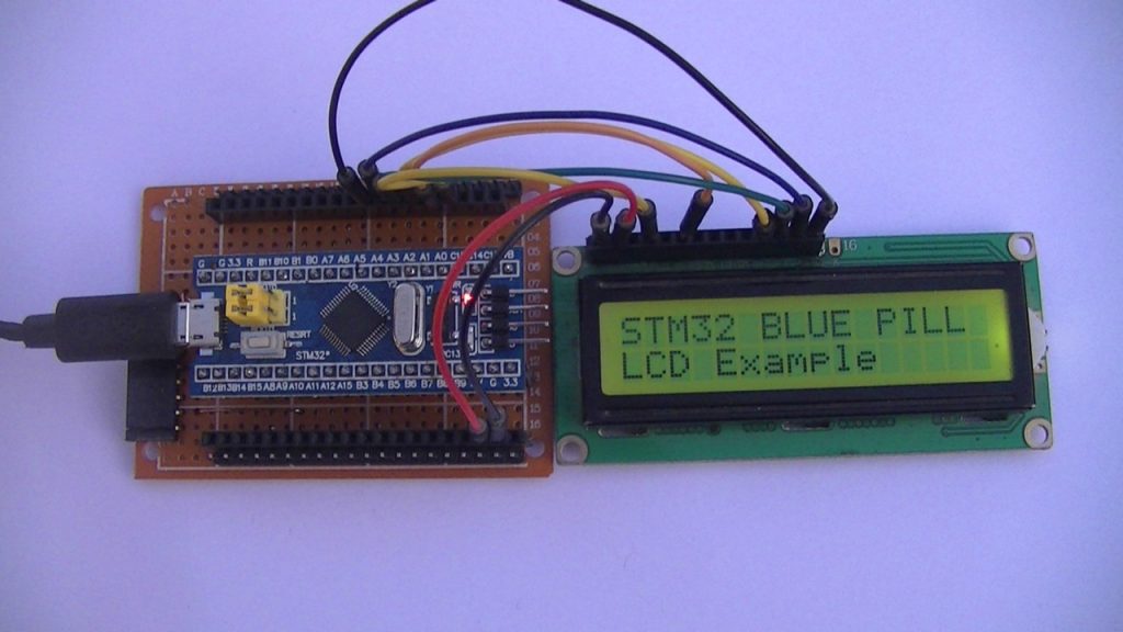
More details about the TM1637 7-segment display module, how it works, and how to interface it with the STM32 Blue Pill board, at this post:
STM32 Blue Pill Interface with TM1637 7-Segment Display Module
The Rotary Encoder:
Generally, the rotary encoder is an electromechanical device that converts angular movements of its shaft into a series of electrical pulses which are counted & analyzed to determine position, speed, and direction of rotation.
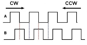
Most rotary encoders operate by producing two signals, let’s say A and B. These signals are generated based on the movement of the shaft and are typically read as quadrature signals, meaning they are 90° out of phase with each other.
As the shaft rotates, the rotary encoder produces a series of pulses on channels A and B. The pulse rate corresponds to the rotating speed, while the pulse count indicates the position change (number of movements).
The direction of rotation can be determined by analyzing the signals generated on channels A and B:
- If A leads B, means that the shaft is rotating in one direction (for example, clockwise).
- If B leads A, means that the shaft is rotating in the opposite direction (for example, counterclockwise).
The position of the rotary encoder shaft, or number of movements, can be determined by counting the pulses on channels A and B.
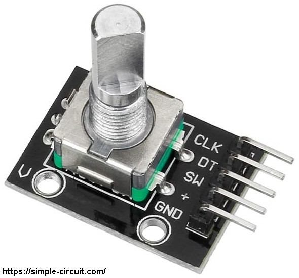
The rotary encoder module used in this project is the one shown below:
This rotary encoder module has 5 pins, as indicated in the PCB: GND, + (+5V or 3.3V), SW (push button output), DT (channel B) and CLK (channel A).
As an addition to the rotary encoder there is a push button at the center of the shaft and three pull up resistors of 10k Ohm connected to pins SW, DT and CLK. With the three pull-up resistors, the normal state of each terminal is logic high.
Interfacing STM32 Blue Pill Board with Rotary Encoder:
This post shows how to print the position of rotary encoder in a 4-digit seven-segment display based on TM1637 driver.
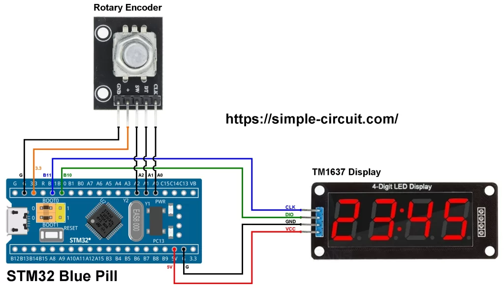
The circuit schematic below shows the connection of STM32 Blue Pill board with rotary encoder and TM1637 display modules.
The rotary encoder module has 5 pins: GND, + , SW, DT (pin B or data pin) and CLK (pin A or clock pin) where:
- GND Pin of rotary encoder module is connected to GND pin of the STM32 Blue Pill board.
- + Pin of rotary encoder module is connected to pin 3.3 of the STM32 Blue Pill board.
- SW Pin of rotary encoder module is connected to pin A2 of the STM32 Blue Pill board.
- DT Pin of rotary encoder module is connected to pin A1 of the STM32 Blue Pill board.
- CLK Pin of rotary encoder module is connected to pin A0 of the STM32 Blue Pill board.
The display is used to show the position of the rotary encoder.
SW Pin of the rotary encoder module is the output of the pushbutton, in this project it is used to reset (clear) the position of the rotary encoder.
To more stabilize the rotary encoder circuit we can add a low pass filter that consists of a resistor and a ceramic capacitor to DT and CLK pins.
The TM1637 module has 4 pins: VCC, GND, DIO, and CLK. They are connected to the STM32 board as follows:
- CLK Pin of the TM1637 module is connected to pin PB11 of the STM32 board.
- DIO Pin of the TM1637 module is connected to pin PB10 of the STM32 board.
- GND Pin of the TM1637 module is connected to GND pin of the STM32 board.
- VCC Pin of the TM1637 module is connected to 5V pin of the STM32 board.
Note that PB10 and PB11 are 5V tolerant pins.
Hardware required:
This is a summary of the parts required to build this project.
- STM32 Blue Pill board —> STM32F103C8T6 32-bit Arm Cortex-M3 MCU datasheet
- TM1637 display module —> TM1637 IC datasheet
- Rotary encoder module
- Jumper wires
- STM32 Microcontroller programmer (ST-Link, USB-to-Serial converter…)
Interfacing STM32 Blue Pill with Rotary Encoder Code:
Arduino IDE (Integrated Development Environment) is used to write project code, the STM32 Blue Pill board has to be added to the IDE before code compilation.
The STM32 Blue Pill board can be installed using Arduino IDE Boards Manager.
The FT232RL USB to serial UART converter is used to program the STM32F103C8T6 microcontroller, the ST-LINK V2 programmer also can be used and it is supported by the Arduino IDE.
A library for the TM1637 simplifies the interfacing code of the STM32 Blue Pill board with the display module. This library is written by ‘Avishay Orpaz’ and contains a useful built-in functions that control the display.
The TM1637 library can be installed through Arduino IDE Library Manager, in the search filter box write “TM1637” and install the one written by ‘Avishay Orpaz’. It also can be downloaded and installed manually, GitHub link is below:
TM1637 Module Arduino Library
Note that this code was tested with TM1637 display library version 1.2.0.
After installing the library, it’s included in the Arduino as:
1 2 | // include TM1637 display module library #include <TM1637Display.h> |
And the TM1637 display module pins are defined in the Arduino code as:
1 2 3 | // define TM1637 Module connection pins #define CLK PB11 // clock pin #define DIO PB10 // data pin |
The TM1637 library is initialized as follows:
1 2 | // Initialize TM1637 display module library TM1637Display display(TM1637_CLK, TM1637_DIO); |
Rotary encoder module pins are defined in Arduino code as shown below:
1 2 3 4 | // Rotary encoder pins #define CLK_PIN PA0 #define DT_PIN PA1 #define SW_PIN PA2 |
The Blue Pill board microcontroller STM32F103C8T6 executes function called EncoderStatus whenever there is change in state occurred at pins CLK_PIN or DT_PIN. The microcontroller then starts reading the state of the two inputs and calculates the position of the rotary encoder with the function EncoderGet.
The external interrupt on change for the two pins is configured as follows:
1 2 3 | // Enable interrupt on change for rotary encoder CLK & DT pins attachInterrupt(digitalPinToInterrupt(CLK_PIN), EncoderStatus, CHANGE); attachInterrupt(digitalPinToInterrupt(DT_PIN), EncoderStatus, CHANGE); |
Rest of code is described through comments.
1 2 3 4 5 6 7 8 9 10 11 12 13 14 15 16 17 18 19 20 21 22 23 24 25 26 27 28 29 30 31 32 33 34 35 36 37 38 39 40 41 42 43 44 45 46 47 48 49 50 51 52 53 54 55 56 57 58 59 60 61 62 63 64 65 66 67 68 69 70 71 72 73 74 75 76 77 78 79 80 81 82 83 84 85 86 87 88 89 90 91 92 93 94 95 96 97 98 99 100 101 | /****************************************************************************** * STM32F103C8T6 Blue Pill board Interface with rotary encode and TM1637 * 4-Digit seven-segment display module. * This example shows how print the position of the rotary encoder on the * TM1637 display. * This is a free software with NO WARRANTY. * https://simple-circuit.com/ /*******************************************************************************/ // Include TM1637 display module library #include <TM1637Display.h> // Define TM1637 Module connection pins #define TM1637_CLK PB11 // clock pin #define TM1637_DIO PB10 // data pin // Initialize TM1637 display module library TM1637Display display(TM1637_CLK, TM1637_DIO); // Rotary encoder pins #define CLK_PIN PA0 #define DT_PIN PA1 #define SW_PIN PA2 void setup() { // Set display brightness (7 maximum brightness and 0 minimum) display.setBrightness(7); display.showNumberDec(0, true); // Pins configuration pinMode(CLK_PIN, INPUT_PULLUP); pinMode(DT_PIN, INPUT_PULLUP); pinMode(SW_PIN, INPUT_PULLUP); // Enable interrupt on change for rotary encoder CLK & DT pins attachInterrupt(digitalPinToInterrupt(CLK_PIN), EncoderStatus, CHANGE); attachInterrupt(digitalPinToInterrupt(DT_PIN), EncoderStatus, CHANGE); } // Variables declaration int8_t quad = 0; // Interrupt Service Routine (ISR) void EncoderStatus(void) { static uint8_t LastRead = 3; uint8_t ThisRead = 0; ThisRead = (digitalRead(CLK_PIN) << 1) | (digitalRead(DT_PIN)); if(ThisRead == LastRead) return; if( bitRead(ThisRead, 0) == bitRead(LastRead, 1) ) quad -= 1; else quad += 1; LastRead = ThisRead; } // Function to calculate latest number of rotary encoder moves int8_t EncoderGet(void) { int8_t val = 0; if( abs(quad) >= 4 ) { val = quad / 4; quad %= 4; } return val; } // Main loop void loop() { static int16_t pos = 0; int8_t tick = EncoderGet(); if(tick) { pos += tick; // Print variable 'i' on the display (decimal format with leading zeros) display.showNumberDec(pos, true); } if( digitalRead(SW_PIN) == 0) // If rotary encoder button pressed { pos = 0; display.showNumberDec(pos, true); } delay(10); // Wait 10 milliseconds } // end of code. |
This above code uses interrupts to detect the transition of rotary encoder outputs.
If the microcontroller can keep reading main loop so that no state change event of rotary encoder output pins will be lost then interrupt is not be required and we can write code that determines the position of the rotary encoder without interrupt.
Also, the Blue Pill board microcontroller STM32F103C8T6 has several hardware Timers that can be configured to work in Encoder Interface Mode. With this mode the microcontroller can calculate the position of the rotary encoder where the change of its output is detected by hardware so that no interrupt is required in the code.
In Encoder Interface Mode the microcontroller can detect the direction of rotation of the rotary encoder and counts the pulses generated so that every positive movement is represented by 4 and every negative movement (the other direction) is represented by -4.
Interfacing STM32 Blue Pill Board with Rotary Encoder Video:
The video below shows a hardware test circuit for STM32 Blue Pill board with rotary encoder and TM1637 display module.
Discover more from Simple Circuit
Subscribe to get the latest posts sent to your email.
can you please do a pure sine wave inverter with feedback project using the blupill