This topic shows how to easily interface the DS1307 real time clock chip with PIC16F887 microcontroller where time and date are displayed on 16×2 LCD screen.
MikroC PRO for PIC compiler is used in this example.
The DS1307 is an 8-pin integrated circuit that uses I2C protocol to communicate with master device (microprocessor, microcontroller …). This small chip can count seconds, minutes, hours, day of the week, day of month, month and year with leap-year up to year 2100.
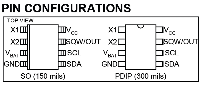
The following image shows the DS1307 pin configurations:
And the following image shows a typical operating circuit for the DS1307 RTC:
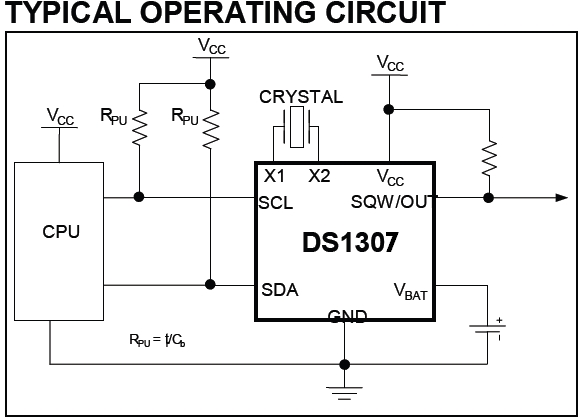
A 3V battery can be connected between VBAT and GND which can be used as a backup supply input. With this battery the DS1307 keeps time running even if the main power source is off.
The DS1307 uses an external 32.768KHz crystal and there is no need to add any resistors or capacitors with it.
More information are in the DS1307 RTC datasheet.
DS1307 RTC library (driver) for mikroC compiler:
To simplify project C code, I wrote a small library for the DS1307. Library functions are listed below.
This driver supports software I2C and hardware I2C (more faster). It will use the software I2C (using mikroC built-in soft I2C library) if the following line is defined in the main code:
#define DS1307_SOFT_I2C
Otherwise the driver will automatically use hardware I2C1 module and it will use hardware I2C2 module if the line below is defined in the main code:
#define DS1307_I2C2
void RTC_Set(RTC_Time *time_t): this function sets time and date (writes time and date to the DS1307) where the variable time_t of type struct (structure) which collects the following unsigned 8-bit integer variables:
seconds, minutes, hours, dow, day, month and year.
Where dow is day of the week (Monday, Tuesday …) and day is month day.
seconds and minutes range: 0 – 59
hours range: 0 – 23 (24-hour format)
dow range: 1 – 7 (1 equals Sunday, 2 equals Monday …)
day range: 1 – 31 (depends on month)
month range: 1 – 12 (1 equals January)
year range: 0 – 99.
RTC_Time *RTC_Get(): reads time and date from the DS1307, this function returns them as a variable of type struct (same as the previous function).
void OSC_Enable(): enables the DS1307 oscillator.
void OSC_Disable(): disables the DS1307 oscillator.
uint8_t RTC_Read_Reg(uint8_t reg_address): this function returns the value stored in register of address reg_address.
void RTC_Write_Reg(uint8_t reg_address, uint8_t reg_value): writes reg_value to register of address reg_address.
void SQWE_Set(SQWE pin_out): this function configures the SQW/OUT pin of the DS1307, where pin_out is one of the following:
OUT_OFF: output is off (internally attached to ground)
OUT_ON: output is on (internally floating)
OUT_1Hz: output is square wave with frequency equals to 1Hz
OUT_4096Hz: output is square wave with frequency equals to 4096Hz
OUT_8192Hz: output is square wave with frequency equals to 8192Hz
OUT_32768Hz: output is square wave with frequency equals to 32768Hz
DS1307 Library for mikroC compiler download:
Driver source file download link is below, installation of this driver is easy, just add it to project folder. Driver full name (with extension) is: DS1307.c.
DS1307 mikroC library
DS1307 Library Example:
This is a small example that shows how to use this library.
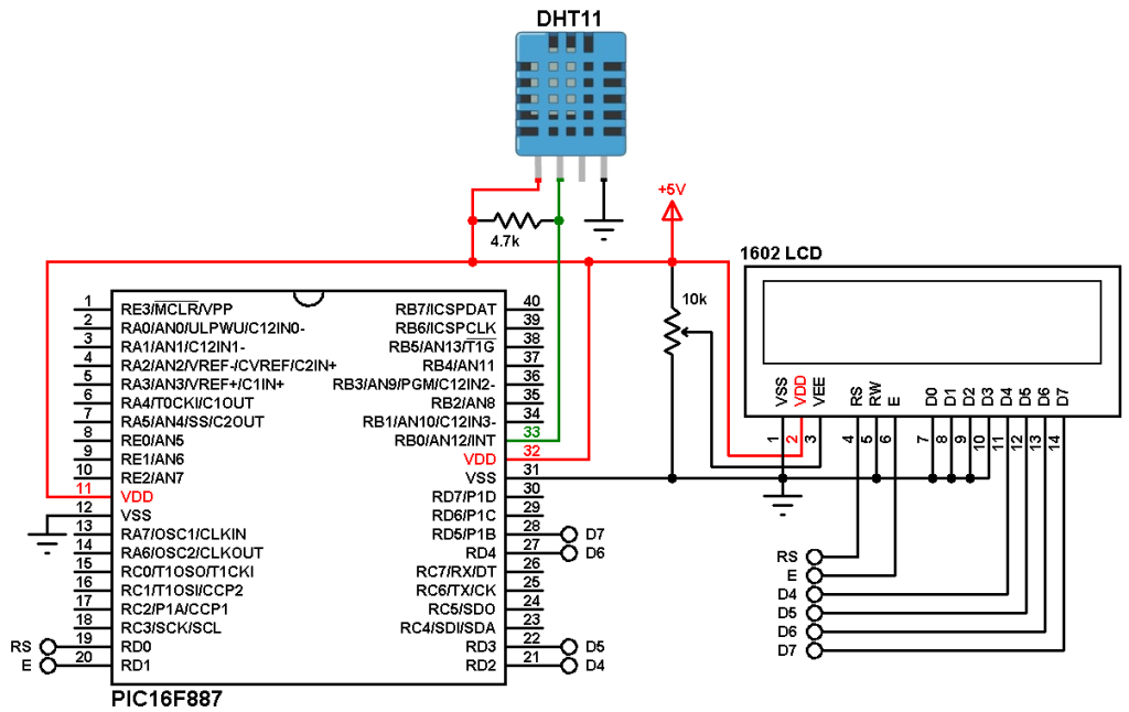
In this example PIC16F887 microcontroller is used, hardware circuit diagram is shown below.
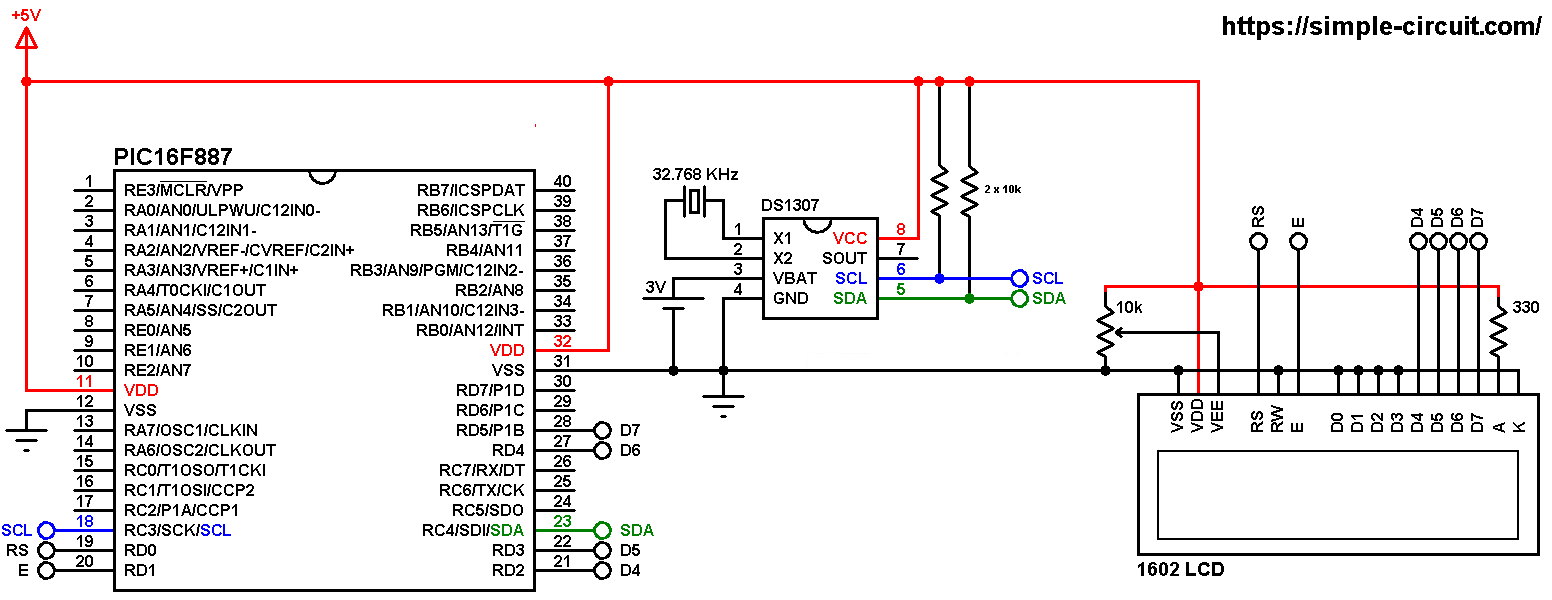
All the grounded terminals are connected together.
SDA and SCL pins of the DS1307 are respectively connected to SDA (RC4) and SCL (RC3) pins of the PIC16F887 microcontroller.
The 1602 LCD screen is used to display time and date where:
RS —> pin RD0
E —> pin RD1
D4 —> pin RD2
D5 —> pin RD3
D6 —> pin RD4
D7 —> pin RD5
VSS, RW, D0, D1, D2, D3 and K are connected to circuit ground
VEE to the variable resistor (or potentiometer) output
VDD to +5V and A to +5V through 330 ohm resistor.
VEE pin is used to control the contrast of the LCD. A (anode) and K (cathode) are the back light LED pins.
In this project the PIC16F887 microcontroller uses its internal oscillator (@ 8MHz) and MCLR pin is configured as input.
C code:
The C code below is for mikroC (PRO for PIC) compiler, it was tested with version 7.2.0.
To be able to compile project C code with no error, a driver (library) for the DS1307 RTC is required, download link is above.
After you download the driver file which named DS1307.c, add it to your project folder.
Full mikroC code:
Configuration words (for PIC16F887 microcontroller):
CONFIG1 = 0x2CD4
CONFIG2 = 0x0700
1 2 3 4 5 6 7 8 9 10 11 12 13 14 15 16 17 18 19 20 21 22 23 24 25 26 27 28 29 30 31 32 33 34 35 36 37 38 39 40 41 42 43 44 45 46 47 48 49 50 51 52 53 54 55 56 57 58 59 60 61 62 63 64 65 66 67 68 69 70 71 72 73 74 75 76 77 78 79 80 81 82 83 84 85 86 87 88 89 | /************************************************************************************** Interfacing PIC16F887 microcontroller with DS1307 RTC. Time and date are displayed on 16x2 LCD. C Code for mikroC PRO for PIC compiler. Internal oscillator used @ 8MHz Configuration words: CONFIG1 = 0x2CD4 CONFIG2 = 0x0700 This is a free software with NO WARRANTY. http://simple-circuit.com/ ***************************************************************************************/ // LCD module connections sbit LCD_RS at RD0_bit; sbit LCD_EN at RD1_bit; sbit LCD_D4 at RD2_bit; sbit LCD_D5 at RD3_bit; sbit LCD_D6 at RD4_bit; sbit LCD_D7 at RD5_bit; sbit LCD_RS_Direction at TRISD0_bit; sbit LCD_EN_Direction at TRISD1_bit; sbit LCD_D4_Direction at TRISD2_bit; sbit LCD_D5_Direction at TRISD3_bit; sbit LCD_D6_Direction at TRISD4_bit; sbit LCD_D7_Direction at TRISD5_bit; // end LCD module connections #include <DS1307.c> // include DS1307 RTC driver source file // DS1307 library variable declaration RTC_Time *mytime; void rtc_print() { char txt[17]; // print time sprinti(txt, "TIME: %02u:%02u:%02u", (int)mytime->hours, (int)mytime->minutes, (int)mytime->seconds); LCD_Out(1, 1, txt); // print date sprinti(txt, "DATE: %02u-%02u-20%02u", (int)mytime->day, (int)mytime->month, (int)mytime->year); LCD_Out(2, 1, txt); } // main function void main() { OSCCON = 0x70; // set internal oscillator to 8MHz delay_ms(1000); // wait a second I2C1_Init(100000); // initialize I2C communication Lcd_Init(); // initialize LCD module Lcd_Cmd(_LCD_CURSOR_OFF); // cursor off Lcd_Cmd(_LCD_CLEAR); // clear LCD // read current time and date from the RTC chip mytime = RTC_Get(); // print them rtc_print(); // set RTC time to 15:43:12 (hh:mm:ss) and date to 25-12-18 (dd-mm-yy) mytime->hours = 15; mytime->minutes = 43; mytime->seconds = 12; mytime->day = 25; mytime->month = 12; mytime->year = 18; // write time and date to the RTC chip RTC_Set(mytime); // enable RTC oscillator OSC_Enable(); // enable SQWE output with frequency of 1Hz SQWE_Set(OUT_1Hz); while(1) { // read current time and date from the RTC chip mytime = RTC_Get(); // print them rtc_print(); delay_ms(200); // wait 100 ms } } // end of code. |
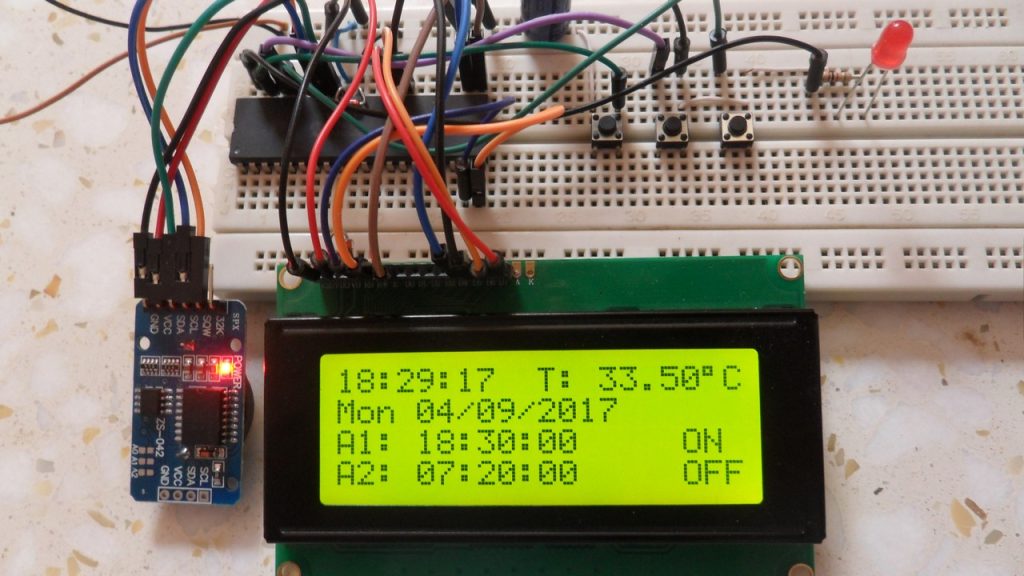
Proteus simulation as well as hardware circuit of the example should give the result shown below (RTC starts updating immediately).
Note that Proteus simulation circuit is not the same as real hardware circuit, project hardware circuit is shown above.

Other projects where DS1307 RTC driver is used:
Discover more from Simple Circuit
Subscribe to get the latest posts sent to your email.
Hello there, I tried to compile this code in mikroc ver. 7.6.0 the problem is I am unable to include header file, the error says can’t open include file ds1307.c please help me out.