This post shows how to build a simple real time clock using PIC18F4550 microcontroller, Nokia 5110 graphical LCD and DS1307 RTC chip. Time and date are displayed on the Nokia 5110 LCD which has a resolution of 84 x 48 pixel and they could be set using two push buttons connected to the PIC18F4550 microcontroller.
The compiler used in this project is CCS PIC C.
To see how to interface the PIC18F4550 with the Nokia 5110 for the first time, visit the post below:
Interfacing PIC18F4550 MCU with NOKIA 5110 LCD
Hardware Required:
- PIC18F4550 microcontroller
- Nokia 5110 LCD screen
- DS1307 RTC —-> datasheet
- 32.768 kHz crystal oscillator
- AMS1117 3V3 voltage regulator
- 10 uF capacitor
- 100 nF ceramic capacitor
- 2 x 10k ohm resistor
- 5 x 3.3k ohm resistor
- 5 x 2.2k ohm resistor
- 2 x push button
- 3V coin cell battery
- 5V power source
- Breadboard
- Jumper wires
PIC18F4550 Clock with Nokia 5110 LCD and DS1307 circuit:
The following image shows project circuit schematic diagram.
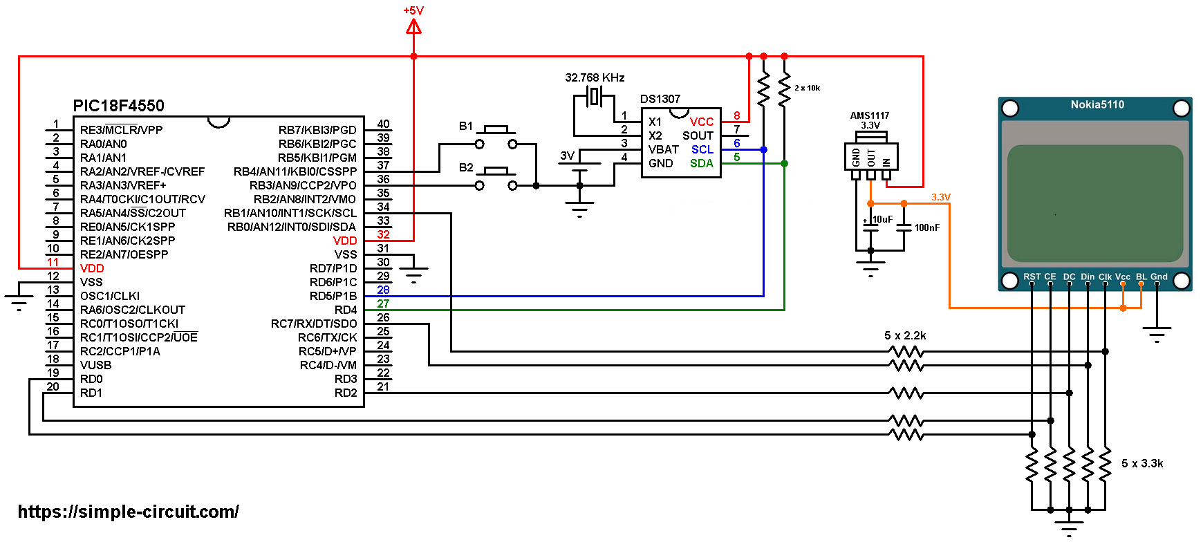
All the grounded terminals are connected together.
DS1307 SDA pin (#5) and SCL pin (#6) are connected to PIC18F4550 RD4 (#27) and RD5 (#28) respectively.
The two push buttons B1 and B2 are for setting time and date. The two buttons are connected to PIC18F4550 pin RB4 (#37) and pin RB3 (#36) respectively for B1 and B2.
In this project the PIC18F4550 uses its internal oscillator and MCLR pin function is disabled.
PIC18F4550 Clock with Nokia 5110 LCD and DS1307 C code:
The C code below is for CCS C compiler, it was tested with version 5.051.
To be able to compile project C code, a driver for the Nokia 5110 LCD is required, download link is below. After you download the driver file which named NOKIA5110.c, add it to your project folder:
Nokia 5110 LCD driver for CCS C compiler
Connection of LCD reset, chip select and data/command pins are defined in the code as:
1 2 3 4 | // define LCD module pin connections #define LCD_RST PIN_D0 // reset pin, optional! #define LCD_CS PIN_D1 // chip select pin, optional! #define LCD_DC PIN_D2 // data/command pin |
I2C Bus (software) is initialized in the code as shown below with SCL mapped to pin RD5 and SDA to pin RD4 (required for the DS1307 RTC chip):
1 | #use I2C(MASTER, SDA = PIN_D4, SCL = PIN_D5) |
Functions used in the code:
int1 debounce (): this function is for button B1 debounce, returns 1 if button is debounced.
void day_display(): displays day of the week (Monday, Tuesday …) on the LCD.
void RTC_display(): displays time, date and day of the week on the LCD. This function calls the previous one for displaying the day of the week.
void wait(): this function is just a delay of 500 ms except that it can be interrupted by the two push buttons (B1 and B2).
int8 edit(int8 x_pos, int8 y_pos, int8 parameter): this function is for setting the real time clock, returns the edited parameter.
Rest of code is described through comments!
Full CCS C code:
1 2 3 4 5 6 7 8 9 10 11 12 13 14 15 16 17 18 19 20 21 22 23 24 25 26 27 28 29 30 31 32 33 34 35 36 37 38 39 40 41 42 43 44 45 46 47 48 49 50 51 52 53 54 55 56 57 58 59 60 61 62 63 64 65 66 67 68 69 70 71 72 73 74 75 76 77 78 79 80 81 82 83 84 85 86 87 88 89 90 91 92 93 94 95 96 97 98 99 100 101 102 103 104 105 106 107 108 109 110 111 112 113 114 115 116 117 118 119 120 121 122 123 124 125 126 127 128 129 130 131 132 133 134 135 136 137 138 139 140 141 142 143 144 145 146 147 148 149 150 151 152 153 154 155 156 157 158 159 160 161 162 163 164 165 166 167 168 169 170 171 172 173 174 175 176 177 178 179 180 181 182 183 184 185 186 187 188 189 190 191 192 193 194 195 196 197 198 199 200 201 202 203 204 205 206 207 208 209 210 211 212 213 214 215 216 217 218 219 220 221 222 223 224 225 226 227 228 229 230 231 232 233 234 235 236 237 238 239 240 241 242 243 244 245 246 247 248 249 250 251 252 | /* * Interfacing PIC18F4550 microcontroller with Nokia 5110 LCD * and DS1307 real time clock chip. * This code works also with DS3231. * C Code for CCS C compiler. * This is a free software with NO WARRANTY. * http://simple-circuit.com/ */ // define LCD module pin connections #define LCD_RST PIN_D0 // reset pin, optional! #define LCD_CS PIN_D1 // chip select pin, optional! #define LCD_DC PIN_D2 // data/command pin // button definitions #define button1 PIN_B4 // button B1 is connected to RB4 pin #define button2 PIN_B3 // button B2 is connected to RB3 pin #include <18F4550.h> #fuses NOMCLR, INTRC_IO, NOWDT, NOPROTECT, NOLVP #use delay(clock = 8MHz) #use spi(SPI1, BAUD = 1000000, MODE = 3, BITS = 8, STREAM = LCD_STREAM) #use I2C(MASTER, SDA = PIN_D4, SCL = PIN_D5) #use fast_io(B) #include <NOKIA5110.c> // include Nokia 5110 LCD driver source file // variable declarations int8 i, second, minute, hour, w_day, day, month, year; // a small function for button1 (B1) debounce int1 debounce () { byte count = 0; for(int8 i = 0; i < 5; i++) { if ( !input(button1) ) count++; delay_ms(10); } if(count > 2) return 1; else return 0; } // function for display day of the week void day_display() { LCD_FillRect(15, 16, 53, 7, FALSE); if ( (w_day == 3) || (w_day == 4) ) LCD_GotoXY(15, 16); else LCD_GotoXY(12, 16); switch(w_day) { case 1: LCD_Print(" SUNDAY "); break; case 2: LCD_Print(" MONDAY "); break; case 3: LCD_Print(" TUESDAY "); break; case 4: LCD_Print("WEDNESDAY"); break; case 5: LCD_Print(" THURSDAY "); break; case 6: LCD_Print(" FRIDAY "); break; default: LCD_Print(" SATURDAY "); } LCD_Display(); } void RTC_display() { // convert BCD to decimal second = (second >> 4) * 10 + (second & 0x0F); minute = (minute >> 4) * 10 + (minute & 0x0F); hour = (hour >> 4) * 10 + (hour & 0x0F); day = (day >> 4) * 10 + (day & 0x0F); month = (month >> 4) * 10 + (month & 0x0F); year = (year >> 4) * 10 + (year & 0x0F); // end conversion // print time LCD_GotoXY(18, 40); printf(LCD_Print, "%02u:%02u:%02u", hour, minute, second); // print date LCD_GotoXY(12, 24); printf(LCD_Print, "%02u/%02u/20%02u", day, month, year); // print day of the week day_display(); } void wait() { int8 j = 0; while(j < 100 && input(button1) && input(button2)) { j++; delay_ms(5); } } int8 edit(int8 x_pos, int8 y_pos, int8 parameter) { while(debounce()); // call debounce function (wait for B1 to be released) while(TRUE) { while(!input(button2)) { parameter++; if(i == 0 && parameter > 31) // if date > 31 ==> date = 1 parameter = 1; if(i == 1 && parameter > 12) // if month > 12 ==> month = 1 parameter = 1; if(i == 2 && parameter > 99) // if year > 99 ==> year = 0 parameter = 0; if(i == 3 && parameter > 23) // if hours > 23 ==> hours = 0 parameter = 0; if(i == 4 && parameter > 59) // if minutes > 59 ==> minutes = 0 parameter = 0; LCD_GotoXY(x_pos, y_pos); printf(LCD_Print,"%02u", parameter); LCD_Display(); delay_ms(200); } LCD_GotoXY(x_pos, y_pos); LCD_Print(" "); LCD_Display(); wait(); LCD_GotoXY(x_pos, y_pos); printf(LCD_Print,"%02u", parameter); LCD_Display(); wait(); if(!input(button1)) // if button B1 is pressed if(debounce()) // call debounce function (make sure if B1 is pressed) { i++; // increment 'i' for the next parameter return parameter; // return parameter value and exit } } } // main function void main() { setup_oscillator(OSC_8MHZ); // set internal oscillator to 8MHz port_b_pullups(TRUE); // enable PORTB internal weak pull-ups delay_ms(1000); // wait 1 second LCD_Begin(); // initialize the LCD LCD_Clear(); // clear the buffer LCD_SetContrast(50); // set LCD contrast LCD_TextSize(1); // set text size to 1 LCD_GotoXY(6, 0); // move cursor to position (6, 0) pixel LCD_Print("DS1307 CLOCK"); LCD_GotoXY(0, 8); // move cursor to position (0, 8) pixel LCD_Print("NOKIA 5110 LCD"); LCD_GotoXY(28, 32); // move cursor to position (28, 32) pixel LCD_Print("TIME:"); LCD_Display(); // print LCD buffer while(TRUE) { if(!input(button1)) // if button B1 is pressed if(debounce()) // call debounce function (make sure if B1 is pressed) { i = 0; while(debounce()); // call debounce function (wait for button B1 to be released) while(TRUE) { while( !input(button2) ) // while button B2 pressed { w_day++; // increment w_day if(w_day > 7) w_day = 1; day_display(); // call day_display function delay_ms(500); // wait 500 ms } LCD_FillRect(15, 16, 53, 7, FALSE); LCD_Display(); wait(); // call wait() function day_display(); // call day_display function wait(); // call wait() function if( !input(button1) ) // if button B1 is pressed break; } day = edit(12, 24, day); // edit date month = edit(30, 24, month); // edit month year = edit(60, 24, year); // edit year hour = edit(18, 40, hour); // edit hours minute = edit(36, 40, minute); // edit minutes // convert decimal to BCD minute = ((minute / 10) << 4) + (minute % 10); hour = ((hour / 10) << 4) + (hour % 10); day = ((day / 10) << 4) + (day % 10); month = ((month / 10) << 4) + (month % 10); year = ((year / 10) << 4) + (year % 10); // end conversion while(debounce()); // call debounce function (wait for button B1 to be released) // write data to the RTC chip i2c_start(); // start I2C i2c_write(0xD0); // RTC chip address i2c_write(0); // send register address i2c_write(0); // reset seconds and start oscillator i2c_write(minute); // write minute value to RTC i2c_write(hour); // write hour value to RTC i2c_write(w_day); // write day of week value to RTC i2c_write(day); // write day value to RTC i2c_write(month); // write month value to RTC i2c_write(year); // write year value to RTC i2c_stop(); // stop I2C delay_ms(200); // wait 200ms } // read current time and date i2c_start(); // start I2C i2c_write( 0xD0); // RTC chip address i2c_write( 0); // send register address i2c_start(); // restart I2C i2c_write(0xD1); // initialize data read second = i2c_read(1); // read seconds from register 0 minute = i2c_read(1); // read minutes from register 1 hour = i2c_read(1); // read hour from register 2 w_day = i2c_read(1); // read day of week from register 3 day = i2c_read(1); // read day from register 4 month = i2c_read(1); // read month from register 5 year = i2c_read(0); // read year from register 6 i2c_stop(); // stop I2C RTC_display(); // print time & date delay_ms(100); // wait 100 ms } } // end of code. |
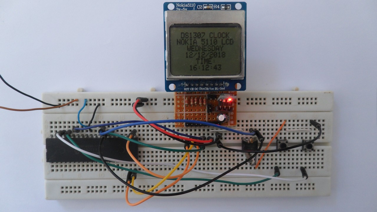
My simple protoboard circuit gave the following result:
Proteus simulation of this project should give the same result as shown in the following video where Arduino UNO is used instead of the PIC18F4550 microcontroller:
Discover more from Simple Circuit
Subscribe to get the latest posts sent to your email.


