This post shows how interface PIC18F4550 microcontroller with Nokia 5110 (Nokia 3310) graphical LCD screen. In this project I’m going to use CCS PIC C compiler.
The name Nokia 5110 (3310) comes from Nokia 5110 (or Nokia 3310) mobile phone. The Nokia 5110 LCD has a controller named PCD8544, it is similar to the Nokia 5110 mobile phone LCD, it uses SPI interface protocol with maximum clock frequency of 4MHz, it requires 5 control pins (at most), it’s low cost and easy to use.
The resolution of this LCD is 84 x 48 which means it has 4032 pixels. This module works with 3.3V only and it doesn’t support 5V (it’s not 5V tolerant), that means interfacing it with 5V microcontroller such as PIC18F4550 may require voltage level shifter.
Nokia 5110 driver for CCS C compiler:
To simplify the interfacing C code, I wrote a simple driver (library) for the Nokia 5110 LCD (PCD8544 controller).
This small driver and graphics library allows us to print texts, draw lines, circles and many other function (listed below). This library is just a .C file named NOKIA5110.C which can be installed by adding it to project folder or CCS C compiler drivers folder (for example: C:\Program Files\CCS\Drivers)
The Nokia 5110 LCD library can be downloaded from the link below:
Nokia 5110 LCD driver for CCS C compiler
The SPI bus has to be initialized in the main code as the example shown below where the hardware SPI module is used with a clock frequency of 1MHz (1000000Hz):
#use spi(SPI1, BAUD = 1000000, MODE = 3, BITS = 8, STREAM = LCD_STREAM)
The other LCD pins also have to be defined in the main code as the example shown below where RST (rest) pin is connected to RD0, CS (chip select) pin is connected to RD1 and DC (data/command) pin is connected to RD2:
#define LCD_RST PIN_D0
#define LCD_CS PIN_D1
#define LCD_DC PIN_D2
Driver functions:
LCD_Begin(): this function initializes the Nokia 5110 LCD.
LCD_SetContrast(con): sets the contrast of the display where: 0 <= con <= 63 .
LCD_Display(): prints data buffer on the display, must be called after any draw action.
LCD_Clear(): clears the whole LCD.
LCD_Fill(): fills the whole LCD (writes all LCD pixels).
LCD_TextSize(t_size): sets text size.
LCD_GotoXY(x, y): move cursor to position (x, y), x and y are in pixel.
LCD_TextWrap(w): sets text wrap, if w = 1 text wrap enabled (default), if w = 0 text wrap disabled.
LCD_Print(c): prints a character c on the LCD.
LCD_Invert(inv): inverts the display, inv may be 1 or 0.
LCD_DrawPixel(x, y, color): draws one pixel on the screen, x and y are the coordinates in pixel, color may be 1 or 0 (1 is default).
LCD_DrawLine(x0, y0, x1, y1, color): draws a line from (x0, y0) to (x1, y1). Color may be 1 or 0, 1 draw and 0 delete, default value is 1 (true).
LCD_DrawHLine(x, y, w, color): draws a horizontal line from (x, y) with width of w. Color can be 1 or 0.
LCD_DrawVLine(x, y, h, color); draws a vertical line from (x, y) with height of h. Color can be 1 or 0.
LCD_DrawRect(x, y, w, h): draws a rectangle from (x, y) with width w and height h.
LCD_FillRect(x, y, w, h, color): fills a rectangle from (x, y) with width w and height h. Color can be 1 or 0.
LCD_DrawRoundRect(x, y, w, h, r): draws round rectangle from (x, y) with width w, height h and radius r.
LCD_FillRoundRect(x, y, w, h, r, color): fills round rectangle from (x, y) with width w, height h & radius r.
LCD_DrawTriangle(x0, y0, x1, y1, x2, y2): draws a triangle with points (x0, y0), (x1, y1) and (x2, y2).
LCD_FillTriangle(x0, y0, x1, y1, x2, y2, color): fills a triangle with points (x0, y0), (x1, y1) and (x2, y2).
LCD_DrawCircle(x0, y0, r): draws a circle from (x0, y0) with radius r.
LCD_FillCircle(x0, y0, r, color): fills a circle from (x0, y0) with radius r.
LCD_DrawCircleHelper(x0, y0, r, cornername): draws a circle helper from (x0, y0) with radius r and cornername.
LCD_FillCircleHelper(x0, y0, r, cornername, delta, color): fills a circle helper from (x0, y0) with radius r and cornername.
LCD_ROMBMP(x, y, *bitmap, w, h, color): draws a bitmap which is stored in ROM.
LCD_RAMBMP(x, y, *bitmap, w, h, color): draws a bitmap which is stored in RAM.
Interfacing PIC18F4550 with Nokia 5110 LCD:
Hardware Required:
- PIC18F4550 microcontroller
- Nokia 5110 (3310) LCD module
- AMS1117 3V3 voltage regulator
- 10 uF capacitor
- 100 nF ceramic capacitor
- 5 x 3.3k ohm resistor
- 5 x 2.2k ohm resistor
- 5V source
- Breadboard
- Jumper wires
Interfacing PIC18F4550 MCU with NOKIA 5110 LCD circuit:
The following image shows project circuit diagram.
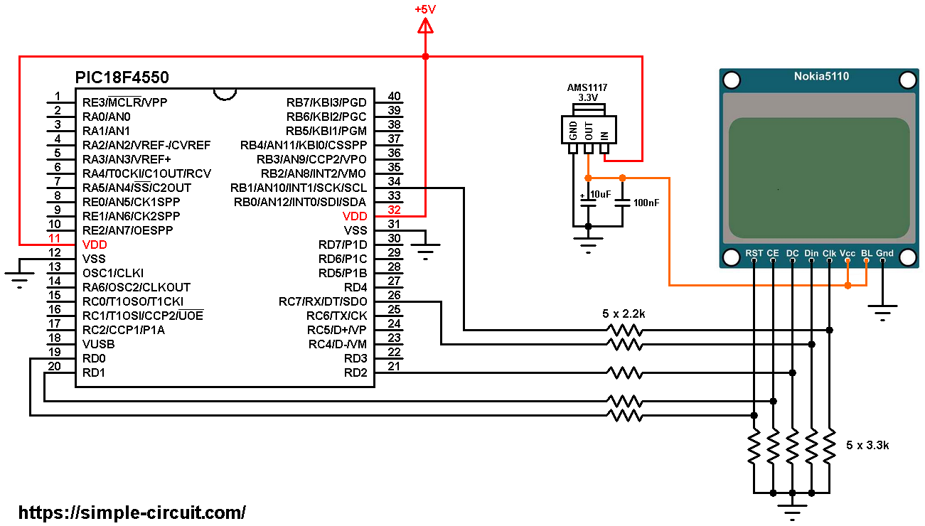
All the grounded terminals are connected together.
The Nokia 5110 which is shown in the circuit diagram has 8 pins (from left to right): RST (reset), CE (chip enable), DC (or D/C: data/command), Din (data in), Clk (clock), VCC (3.3V), BL (back light) and Gnd (ground).
As mentioned above, the Nokia 5110 LCD works with 3.3V only (power supply and control lines). The LCD module is supplied with 3.3V which comes from the AMS1117 3V3 voltage regulator, this regulator steps down the 5V into 3.3V.
All PIC18F4550 microcontroller output pins are 5V, connecting a 5V pin to the Nokia 5110 LCD could damage its controller circuit!
To connect the PIC18F4550 to the LCD module, I used voltage divider for each line which means there are 5 voltage dividers. Each voltage divider consists of 2.2k and 3.3k resistors, this drops the 5V into 3V which is sufficient.
So, the Nokia 5110 LCD pins are connected to PIC18F4550 MCU as follows (each one through voltage divider):
RST (reset) pin is connected to pin RD0 (#19)
CE (chip enable) pin is connected to pin RD1 (#20)
DC (data/command) pin is connected to pin RD2 (#21)
DIN (data in) pin is connected to pin RC7 (#26)
CLK (clock) pin is connected to pin RB1 (#34)
VCC and BL are connected to AMS1117 3V3 regulator output pin and GND is connected to circuit ground (0V).
In this project the PIC18F4550 uses its internal oscillator and MCLR pin function is disabled.
Interfacing PIC18F4550 MCU with NOKIA 5110 LCD C code:
The C code below is for CCS C compiler, it was tested with version 5.051.
To be able to compile project C code, a driver for the Nokia 5110 LCD is required, download link is above. After you download driver file which named NOKIA5110.c, add it to your project folder!
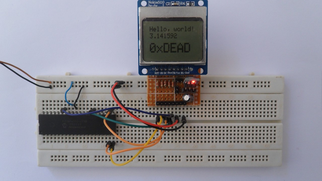
1 2 3 4 5 6 7 8 9 10 11 12 13 14 15 16 17 18 19 20 21 22 23 24 25 26 27 28 29 30 31 32 33 34 35 36 37 38 39 40 41 42 43 44 45 46 47 48 49 50 51 52 53 54 55 56 57 58 59 60 61 62 63 64 65 66 67 68 69 70 71 72 73 74 75 76 77 78 79 80 81 82 83 84 85 86 87 88 89 90 91 92 93 94 95 96 97 98 99 100 101 102 103 104 105 106 107 108 109 110 111 112 113 114 115 116 117 118 119 120 121 122 123 124 125 126 127 128 129 130 131 132 133 134 135 136 137 138 139 140 141 142 143 144 145 146 147 148 149 150 151 152 153 154 155 156 157 158 159 160 161 162 163 164 165 166 167 168 169 170 171 172 173 174 175 176 177 178 179 180 181 182 183 184 185 186 187 188 189 190 191 192 193 194 195 196 197 198 199 200 201 202 203 204 205 206 207 208 209 210 211 212 213 214 215 216 217 218 219 220 221 222 223 224 225 226 227 228 229 230 231 232 233 234 235 236 237 238 239 240 241 242 243 244 245 246 247 248 249 250 251 252 253 254 255 256 257 258 259 260 261 262 263 264 265 266 267 268 269 270 271 272 273 274 275 276 277 278 279 280 281 282 283 284 285 286 287 288 289 290 291 292 293 294 295 296 297 298 299 300 301 302 303 304 305 306 307 308 309 310 311 312 | /* * Interfacing PIC18F4550 microcontroller with NOKIA 5110 LCD. * C Code for CCS C compiler. * This is a free software with NO WARRANTY. * http://simple-circuit.com/ */ // define LCD module connections #define LCD_RST PIN_D0 // reset pin, optional! #define LCD_CS PIN_D1 // chip select pin, optional! #define LCD_DC PIN_D2 // data/command pin #include <18F4550.h> #fuses NOMCLR, INTRC_IO, NOWDT, NOPROTECT, NOLVP #use delay(clock = 8MHz) #use spi(SPI1, BAUD = 1000000, MODE = 3, BITS = 8, STREAM = LCD_STREAM) #include <NOKIA5110.c> // include Nokia 5110 LCD driver source file // Microchip bitmap ROM int8 microchip_bmp[] = { 0x00, 0x00, 0x00, 0x00, 0x00, 0x00, 0x00, 0x00, 0x00, 0x00, 0x00, 0x00, 0x00, 0x00, 0x00, 0x00, 0x00, 0x00, 0x00, 0x00, 0x00, 0x00, 0x00, 0x00, 0x00, 0x00, 0x00, 0x00, 0x00, 0x00, 0x00, 0x00, 0x00, 0x80, 0xC0, 0xC0, 0xE0, 0xE0, 0xE0, 0xF0, 0xF0, 0xF0, 0xF0, 0xF0, 0xF0, 0xE0, 0xE0, 0xC0, 0x80, 0x00, 0x00, 0x00, 0x00, 0x00, 0x00, 0x00, 0x00, 0x00, 0x00, 0x00, 0x00, 0x00, 0x00, 0x00, 0x00, 0x00, 0x00, 0x00, 0x00, 0x00, 0x00, 0x00, 0x00, 0x00, 0x00, 0x00, 0x00, 0x00, 0x00, 0x00, 0x00, 0x00, 0x00, 0x00, 0x00, 0x00, 0x00, 0x00, 0x00, 0x00, 0x00, 0x00, 0x00, 0x00, 0x00, 0x00, 0x00, 0x00, 0x00, 0x00, 0x00, 0x00, 0x00, 0x00, 0x00, 0x00, 0x00, 0x00, 0x00, 0x00, 0x00, 0x00, 0x00, 0xE0, 0xF8, 0xFE, 0xFF, 0xFF, 0xFF, 0x9F, 0x07, 0x03, 0x07, 0x0F, 0x3F, 0xFF, 0xFF, 0xDF, 0x0F, 0x07, 0x03, 0x07, 0x1F, 0x7E, 0xF8, 0xF0, 0xC0, 0x00, 0x00, 0x00, 0x00, 0x00, 0x00, 0x00, 0x00, 0x00, 0x00, 0x00, 0x00, 0x00, 0x00, 0x00, 0x00, 0x00, 0x00, 0x00, 0x00, 0x00, 0x00, 0x00, 0x00, 0x00, 0x00, 0x00, 0x00, 0x00, 0x00, 0x00, 0x00, 0x00, 0x00, 0x00, 0x00, 0x00, 0x00, 0x00, 0x00, 0x00, 0x00, 0x00, 0x00, 0x00, 0x00, 0x00, 0x00, 0x00, 0x00, 0x00, 0x00, 0x00, 0x00, 0x00, 0x00, 0x00, 0x00, 0x00, 0x00, 0x1F, 0x0F, 0x03, 0x01, 0x01, 0x83, 0xEF, 0xFE, 0xFC, 0xF0, 0xC0, 0x00, 0x00, 0x03, 0x07, 0xDF, 0xFE, 0xF8, 0xE0, 0xC0, 0x00, 0x00, 0x03, 0x0F, 0x3F, 0x3E, 0x00, 0x00, 0x00, 0x00, 0x00, 0x00, 0x00, 0x00, 0x00, 0x00, 0x00, 0x00, 0x00, 0x00, 0x00, 0x00, 0x00, 0x00, 0x00, 0x00, 0x00, 0x00, 0x00, 0x00, 0x00, 0x00, 0x00, 0x00, 0x00, 0x00, 0x00, 0x00, 0x00, 0x00, 0x00, 0x00, 0x00, 0x00, 0x00, 0x00, 0x00, 0x00, 0x00, 0x00, 0x00, 0x00, 0x00, 0x00, 0x00, 0x00, 0x00, 0x00, 0x00, 0x00, 0x00, 0x00, 0x00, 0x00, 0x00, 0x00, 0x00, 0x06, 0x0F, 0x1F, 0x1F, 0x3F, 0x3F, 0x3F, 0x7F, 0x7F, 0x7E, 0x7E, 0x7F, 0x7F, 0x3F, 0x3F, 0x3F, 0x1F, 0x0F, 0x0C, 0x00, 0x00, 0x00, 0x00, 0x00, 0x00, 0x00, 0x00, 0x00, 0x00, 0x00, 0x00, 0x00, 0x00, 0x00, 0x00, 0x00, 0x00, 0x00, 0x00, 0x00, 0x00, 0x00, 0x00, 0x00, 0x00, 0x00, 0x00, 0x00, 0x00, 0x00, 0x00, 0x00, 0x00, 0x00, 0x00, 0x00, 0x00, 0x00, 0x80, 0xF8, 0xFF, 0x3F, 0xFC, 0xE0, 0x80, 0xE0, 0xFC, 0x3F, 0xFF, 0xF8, 0x80, 0x00, 0xFC, 0xFC, 0x00, 0xF8, 0xFC, 0x0C, 0x0C, 0x0C, 0x0C, 0x0C, 0x18, 0x00, 0xFC, 0xFC, 0x8C, 0x8C, 0x8C, 0xFC, 0x78, 0x00, 0xF8, 0xFC, 0x0C, 0x0C, 0x0C, 0x0C, 0xFC, 0xF8, 0x00, 0xF8, 0xFC, 0x0C, 0x0C, 0x0C, 0x0C, 0x0C, 0x18, 0x00, 0xFC, 0xFC, 0xC0, 0xC0, 0xC0, 0xFC, 0xFC, 0x00, 0xFC, 0xFC, 0x00, 0xFC, 0xFC, 0x8C, 0x8C, 0x8C, 0xFC, 0xF8, 0x00, 0x00, 0x00, 0x00, 0x00, 0x00, 0x00, 0x00, 0x00, 0x00, 0x00, 0x00, 0x00, 0x00, 0x0F, 0x0F, 0x01, 0x00, 0x00, 0x03, 0x07, 0x03, 0x00, 0x00, 0x01, 0x0F, 0x0F, 0x00, 0x0F, 0x0F, 0x00, 0x07, 0x0F, 0x0C, 0x0C, 0x0C, 0x0C, 0x0C, 0x06, 0x00, 0x0F, 0x0F, 0x01, 0x01, 0x01, 0x0F, 0x0E, 0x00, 0x07, 0x0F, 0x0C, 0x0C, 0x0C, 0x0C, 0x0F, 0x07, 0x00, 0x07, 0x0F, 0x0C, 0x0C, 0x0C, 0x0C, 0x0C, 0x06, 0x00, 0x0F, 0x0F, 0x00, 0x00, 0x00, 0x0F, 0x0F, 0x00, 0x0F, 0x0F, 0x00, 0x0F, 0x0F, 0x01, 0x01, 0x01, 0x01, 0x00, 0x00, 0x00, 0x00, 0x00, 0x00, 0x00, 0x00, 0x00 }; void testdrawcircle(void) { for (int8 i = 0; i < LCDHEIGHT; i += 2) { LCD_DrawCircle(LCDWIDTH/2, LCDHEIGHT/2, i); LCD_Display(); delay_ms(10); } } void testfillrect(void) { int1 color = TRUE; for (int8 i = 0; i < LCDHEIGHT/2; i += 3) { // alternate colors LCD_FillRect(i, i, LCDWIDTH - i*2, LCDHEIGHT - i*2, color); LCD_Display(); delay_ms(10); if(color) color = FALSE; else color = TRUE; } } void testdrawtriangle(void) { for (int8 i = 0; i < LCDHEIGHT/2; i += 5) { LCD_DrawTriangle(LCDWIDTH/2, LCDHEIGHT/2 - i, LCDWIDTH/2 - i, LCDHEIGHT/2 + i, LCDWIDTH/2 + i, LCDHEIGHT/2 + i); LCD_Display(); delay_ms(10); } } void testfilltriangle(void) { int1 color = TRUE; for (signed int16 i = LCDHEIGHT/2; i > 0; i -= 5) { LCD_FillTriangle(LCDWIDTH/2, LCDHEIGHT/2 - i, LCDWIDTH/2 - i, LCDHEIGHT/2 + i, LCDWIDTH/2 + i, LCDHEIGHT/2 + i, color); if(color) color = FALSE; else color = TRUE; LCD_Display(); delay_ms(10); } } void testdrawroundrect(void) { for (int8 i = 0; i < LCDHEIGHT / 2 - 2; i += 2) { LCD_DrawRoundRect(i, i, LCDWIDTH - 2 * i, LCDHEIGHT - 2 * i, LCDHEIGHT / 4 - i / 2); LCD_Display(); delay_ms(10); } } void testfillroundrect(void) { int1 color = TRUE; for (int8 i = 0; i < LCDHEIGHT / 2 - 2; i += 2) { LCD_FillRoundRect(i, i, LCDWIDTH - 2 * i, LCDHEIGHT - 2 * i, LCDHEIGHT / 4 - i / 2, color); if(color) color = FALSE; else color = TRUE; LCD_Display(); delay_ms(10); } } void testdrawrect(void) { for (int8 i = 0; i < LCDHEIGHT/2; i += 2) { LCD_DrawRect(i, i, LCDWIDTH - 2*i, LCDHEIGHT - 2*i); LCD_Display(); delay_ms(10); } } void testdrawline() { signed int16 i; for (i = 0; i < LCDWIDTH; i += 4) { LCD_DrawLine(0, 0, i, LCDHEIGHT - 1); LCD_Display(); delay_ms(10); } for (i = 0; i < LCDHEIGHT; i += 4) { LCD_DrawLine(0, 0, LCDWIDTH - 1, i); LCD_Display(); delay_ms(10); } delay_ms(250); LCD_Clear(); for (i = 0; i < LCDWIDTH; i += 4) { LCD_DrawLine(0, LCDHEIGHT - 1, i, 0); LCD_Display(); delay_ms(10); } for (i = LCDHEIGHT - 1; i >= 0; i -= 4) { LCD_DrawLine(0, LCDHEIGHT - 1, LCDWIDTH - 1, i); LCD_Display(); delay_ms(10); } delay_ms(250); LCD_Clear(); for (i = LCDWIDTH - 1; i >= 0; i -= 4) { LCD_DrawLine(LCDWIDTH - 1, LCDHEIGHT - 1, i, 0); LCD_Display(); delay_ms(10); } for (i = LCDHEIGHT - 1; i >= 0; i -= 4) { LCD_DrawLine(LCDWIDTH - 1, LCDHEIGHT - 1, 0, i); LCD_Display(); delay_ms(10); } delay_ms(250); LCD_Clear(); for (i = 0; i < LCDHEIGHT; i += 4) { LCD_DrawLine(LCDWIDTH - 1, 0, 0, i); LCD_Display(); delay_ms(10); } for (i = 0; i < LCDWIDTH; i += 4) { LCD_DrawLine(LCDWIDTH - 1, 0, i, LCDHEIGHT - 1); LCD_Display(); delay_ms(10); } delay_ms(250); } void main() { setup_oscillator(OSC_8MHZ); // set internal oscillator to 8MHz delay_ms(1000); // wait 1 second // initialize the LCD LCD_Begin(); // clear the buffer LCD_Clear(); // set LCD contrast LCD_SetContrast(50); // draw bitmap image stored in PIC ROM // (x, y) = (0, 0), (width, height) = (84, 84) LCD_ROMBMP(0, 0, microchip_bmp, 84, 48); // Show the display buffer on the hardware. // NOTE: You _must call LCD_Display() after making any drawing commands // to make them visible on the display hardware! LCD_Display(); delay_ms(5000); LCD_Clear(); // print text LCD_TextSize(1); // set text size to 1 LCD_GotoXY(0, 0); // move cursor to postion (0, 0) pixel LCD_Print("PIC18F4550 + NOKIA 5110 LCD"); LCD_Display(); delay_ms(5000); // draw a single pixel LCD_DrawPixel(10, 10); LCD_Display(); delay_ms(2000); LCD_Clear(); // draw many lines testdrawline(); delay_ms(2000); LCD_Clear(); // draw rectangles testdrawrect(); LCD_Display(); delay_ms(2000); LCD_Clear(); // draw multiple rectangles testfillrect(); LCD_Display(); delay_ms(2000); LCD_Clear(); // draw mulitple circles testdrawcircle(); LCD_Display(); delay_ms(2000); LCD_Clear(); // draw a circle, 10 pixel radius LCD_FillCircle(LCDWIDTH/2, LCDHEIGHT/2, 20); LCD_Display(); delay_ms(2000); LCD_Clear(); testdrawroundrect(); LCD_Display(); delay_ms(2000); LCD_Clear(); testfillroundrect(); LCD_Display(); delay_ms(2000); LCD_Clear(); testdrawtriangle(); LCD_Display(); delay_ms(2000); LCD_Clear(); testfilltriangle(); LCD_Display(); delay_ms(2000); LCD_Clear(); // text display tests LCD_GotoXY(2, 2); LCD_Print("Hello, world!"); LCD_GotoXY(2, 12); printf(LCD_Print, "%.6f", 3.141592); LCD_GotoXY(2, 26); LCD_TextSize(2); // set text size to 2 printf(LCD_Print, "0x%LX", 0xDEAD); LCD_Display(); delay_ms(2000); while(TRUE) { // invert the display LCD_Invert(TRUE); delay_ms(1000); LCD_Invert(FALSE); delay_ms(1000); } } // end of code. |
The result of my simple hardware circuit is shown in the following video:
and the video below shows Proteus simulation of the project (note that Proteus simulation circuit is not the same as the real hardware circuit, project hardware circuit diagram is shown above!):
Proteus simulation file download link is below, use version 8.6 or higher to open it:
PIC18F4550 and Nokia 5110 Proteus simulation
Projects where Nokia 5110 LCD is used:
PIC18F4550 Interface with DHT11 sensor and Nokia 5110 LCD
Interfacing PIC18F4550 with Nokia 5110 LCD and DHT22 sensor
Real Time Clock using PIC18F4550, Nokia 5110 LCD and DS1307
Interfacing PIC18F4550 with Nokia 5110 LCD and DS3231 RTC
Digital Thermometer using PIC18F4550, Nokia 5110 LCD and DS18B20
Interfacing PIC18F4550 MCU with BMP280 sensor and Nokia 5110 LCD
Weather Station using PIC18F4550, BME280 Sensor and Nokia 5110 LCD
Discover more from Simple Circuit
Subscribe to get the latest posts sent to your email.


13 304 error: Can’t open include file “18f4550.h” #include
Can not record in eeprom memory using this type of screens, or is there any way to do it?
consulta porque no me deja guardar datos en la eeprom , se tilda la pantalla!
si lo estoy haciendo con el 18f2550 , ahora una consulta estoy haciendo un voltimetro y solo me muestra hasta 4,5 volt que puede ser?
si uso el pic 18f2550 podría servirme , necesito un pic mas chico, como declaro los pines en un pic 18f2550
Yes, it will work with PIC18F2550 microcontroller.
en el pic 16f887 se podria ? y como declaro los pines ?
You can build this project using microcontroller with at least 1KB of RAM space.
The PIC16F887 has only 368 bytes.
ya lo solucione , consulta se puede usar otro pic , el 16f886?
You can not build this project with PIC16F886 MCU because it has very small RAM (only 368 bytes). You need a MCU with at least 1kB of RAM, the PIC18F4550 has 2kB.
como hago un voltimetro , estoy tratando y no me deja anidar funciones