This topic shows how to make a simple weather station using PIC18F4550 microcontroller, BME280 sensor and Nokia 5110 graphical LCD screen with 84×48 pixel resolution.
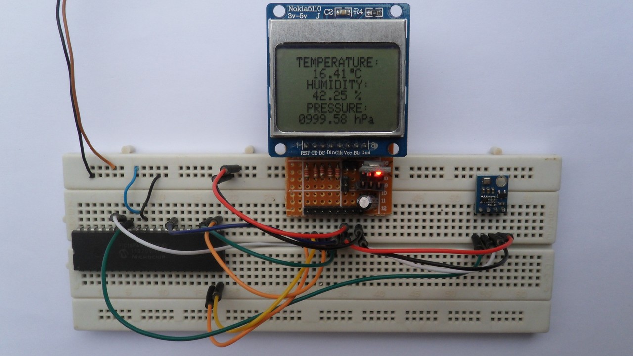
In this project the PIC18F4550 MCU reads weather data (pressure, temperature and humidity) from the BME280 sensor and prints it on the Nokia 5110 LCD screen.
In this project the BME280 sensor is used in I2C mode and the compiler used is CCS PIC C.
To see how to interface the PIC18F4550 with the Nokia 5110 for the first time, visit the post below: Interfacing PIC18F4550 MCU with NOKIA 5110 LCD
The BME280 sensor from Bosch Sensortec is a low cost digital pressure, temperature and humidity sensor with good accuracy. Because pressure changes with altitude we can use it as an altimeter with ±1 meter accuracy (pressure accuracy = ±1 hPa). Some parameters of the sensor are listed below:
Pressure range: 300 … 1100 hPa (equivalent to +9000…-500m above/below sea level)
Pressure resolution: 0.01 hPa ( < 10 cm)
Temperature range: -40 … 85 °C
Temperature resolution: 0.01 °C
Humidity range: 0 … 100 %
Interface: I2C and SPI
Supply voltage range: 1.71 … 3.6 V
The BME280 chip works with maximum voltage of 3.6V (supply voltage range is from 1.71 to 3.6V) which means we’ve to use a 3V3 voltage regulator to supply it from a 5V source.
Also, if we’re working with a 5V system (development board, microcontroller …) like the PIC18F4550 microcontroller we’ve to use a voltage level shifter (level converter) which converts the 3.3V (comes from the BME280 chip) into 5V (goes to the PIC18F4550) and vice versa. This level shifter is for the I2C bus lines (clock and data).
Some BME280 modules come with 3V3 voltage regulator and level shifter like the one provided by Adafruit Industries which is shown below.
A module like this can be used with 3.3V or 5V system without any problem.

In this example I’m going to use a Chinese BME280 module which has a 3.3V regulator and level shifter, this means circuit connection will be more easier!
Hardware Required:
- PIC18F4550 microcontroller
- Nokia 5110 LCD screen
- BME280 sensor module with 3.3V regulator and level shifter —-> BME280 datasheet
- AMS1117 3V3 voltage regulator
- 10 uF capacitor
- 100 nF ceramic capacitor
- 5 x 3.3k ohm resistor
- 5 x 2.2k ohm resistor
- 5V source
- Breadboard
- Jumper wires
PIC18F4550 with BME280 sensor and Nokia 5110 LCD circuit:
The following image shows project circuit schematic diagram.
Note that the BME280 module shown in the circuit diagram has a 3.3V regulator and level shifter.

All the grounded terminals are connected together.
Generally, the BME280 sensor module has at least 4 pins because it can work in SPI mode or I2C mode. For the I2C mode we need 4 pins: VCC, GND, SDA and SCL where:
VCC is the supply pin, it is connected to +5V
GND (ground) is connected to circuit ground (0V)
SDA is I2C bus serial data line, connected to PIC18F4550 pin RB0 (#33)
SCL is I2C bus serial clock line, connected to PIC18F4550 pin RB1 (#34).
Nokia 5110 LCD pins are connected to PIC18F4550 microcontroller as follows (each one through voltage divider where each voltage divider consists of 2.2k and 3.3k resistor):
RST (reset) pin is connected to PIC18F4550 RD0 (#19)
CE (chip enable) pin is connected to PIC18F4550 RD1 (#20)
DC (data/command) pin is connected to PIC18F4550 RD2 (#21)
DIN (data in) pin is connected to PIC18F4550 RD3 (#22)
CLK (clock) pin is connected to PIC18F4550 RD4 (#27).
VCC and BL are connected to 3.3V that comes from the voltage regulator output AMS1117 3V3.
GND is connected to circuit ground (0V).
In this project the PIC18F4550 uses its internal oscillator and MCLR pin function is disabled.
PIC18F4550 with BME280 sensor and Nokia 5110 LCD C code:
The C code below is for CCS C compiler, it was tested with version 5.051.
To be able to compile the C code below, 2 libraries are required:
The first library is a driver for the Nokia 5110 LCD, its full name is NOKIA5110.c, download link is the one below:
Nokia 5110 LCD driver for CCS C compiler
The second library is for the BME280 sensor which could be downloaded from the following link, its name is BME280_Lib.c:
BME280 CCS C driver
The installation of the two drivers is easy, just add them to project folder or CCS C drivers folder (for example C:\Program Files (x86)\CCS\Drivers).
For more details about the BME280 library for CCS C compiler, take a look at this post:
BME280 pressure, temperature and humidity sensor with PIC MCU
The connection of the LCD pins RST, CE, DC, DIN and CLK is defined in the code as shown below where software SPI is used:
1 2 3 4 5 6 | // define LCD module connections #define LCD_RST PIN_D0 // reset pin, optional! #define LCD_CS PIN_D1 // chip select pin, optional! #define LCD_DC PIN_D2 // data/command pin #define LCD_DAT PIN_D3 // data in pin (MOSI) #define LCD_CLK PIN_D4 // clock pin |
Software SPI is initialized as shown below:
1 | #use SPI(DO = LCD_DAT, CLK = LCD_CLK, MODE = 3, BITS = 8, STREAM = LCD_STREAM) |
In this project I used software SPI because the PIC18F4550 has one MSSP module which could be configured as SPI or I2C (the I2C is needed for the BME280 sensor).
As any other I2C device, the BME280 sensor has an I2C slave address which is 0xEC or 0xEE. This address depends on the connection of the SDO pin (used for SPI mode as serial data out or MISO), if the SDO pin is connected (directly or through resistor) to VCC (3.3V) the address will be 0xEE, and if it’s connected to GND the address will be 0xEC.
The default I2C address of the library is defined as 0xEE and my device I2C address is 0xEC.
In the code, the definition of the I2C slave address is as shown below:
1 2 | // define device I2C address: 0xEC or 0xEE (0xEE is library default address) #define BME280_I2C_ADDRESS 0xEC |
The BME280 sensor is initialized with the function BME280_begin(MODE_NORMAL) which returns 1 if ok and 0 if error. In the code the initialization of the sensor is as shown below:
1 2 3 4 5 6 7 8 9 10 | // initialize the BME280 sensor if(BME280_begin(MODE_NORMAL) == 0) { // connection error or device address wrong! LCD_GotoXY(0, 0); LCD_Print("Connection"); LCD_GotoXY(0, 8); LCD_Print("error!"); LCD_Display(); while(TRUE); // stay here } |
The LCD displays “connection error!” if there was an error while initializing the device.
Reading the values of temperature, humidity and pressure is done as shown below.
Note that the library returns the temperature in hundredths °C which means we’ve to divide it by 100, it returns the humidity in relative humidity percent (rH%) in 1024 steps which means we’ve to divide it by 1024 and it returns the pressure in Pa, to get the pressure in hPa we’ve to divide it by 100.
1 2 3 4 5 | // Read temperature (in hundredths °C), pressure (in Pa) // and humidity (in 1024 steps rH%) values from BME280 sensor. BME280_readTemperature(&temp); // read temperature BME280_readHumidity(&humi); // read humidity BME280_readPressure(&pres); // read pressure |
Temperature, humidity and pressure values are displayed on the NOKIA 5110 LCD.
1 bar = 10000 Pa = 100 hPa. ( 1 hPa = 100 Pa)
Pa: Pascal
hPa: hectoPascal
Full CCS C Code:
1 2 3 4 5 6 7 8 9 10 11 12 13 14 15 16 17 18 19 20 21 22 23 24 25 26 27 28 29 30 31 32 33 34 35 36 37 38 39 40 41 42 43 44 45 46 47 48 49 50 51 52 53 54 55 56 57 58 59 60 61 62 63 64 65 66 67 68 69 70 71 72 73 74 75 76 77 78 79 80 81 82 83 84 85 86 87 88 89 90 91 92 93 94 95 96 97 98 99 100 101 | /* * Weather station using PIC18F4550 microcontroller, BME280 sensor * and Nokia 5110 graphical LCD. * BME280 is barometric pressure, temperature and humidity sensor. * C Code for CCS C compiler. * This is a free software with NO WARRANTY. * http://simple-circuit.com/ */ // define LCD module connections #define LCD_RST PIN_D0 // reset pin, optional! #define LCD_CS PIN_D1 // chip select pin, optional! #define LCD_DC PIN_D2 // data/command pin #define LCD_DAT PIN_D3 // data in pin (MOSI) #define LCD_CLK PIN_D4 // clock pin // define device I2C address: 0xEC or 0xEE (0xEE is library default address) #define BME280_I2C_ADDRESS 0xEC #include <18F4550.h> #fuses NOMCLR, INTRC_IO, NOWDT, NOPROTECT, NOLVP #use delay(clock = 8MHz) #use I2C(MASTER, I2C1, FAST = 400000, STREAM = BME280_STREAM) #use SPI(DO = LCD_DAT, CLK = LCD_CLK, MODE = 3, BITS = 8, STREAM = LCD_STREAM) #include <NOKIA5110.c> // include Nokia 5110 LCD driver source file #include <BME280_Lib.c> // include BME280 sensor driver source file // main function void main() { setup_oscillator(OSC_8MHZ); // set internal oscillator to 8MHz delay_ms(1000); // wait 1 second // initialize the LCD LCD_Begin(); // clear the buffer LCD_Clear(); // set LCD contrast LCD_SetContrast(62); LCD_TextSize(1); // set text size to 1 // initialize the BME280 sensor if(BME280_begin(MODE_NORMAL) == 0) { // connection error or device address wrong! LCD_GotoXY(0, 0); LCD_Print("Connection"); LCD_GotoXY(0, 8); LCD_Print("error!"); LCD_Display(); while (TRUE); // stay here! } LCD_GotoXY(7, 0); LCD_Print("TEMPERATURE:"); LCD_GotoXY(16, 16); LCD_Print("HUMIDITY:"); LCD_GotoXY(16, 33); LCD_Print("PRESSURE:"); LCD_Display(); // print LCD buffer signed int32 temp; unsigned int32 pres, humi; while(TRUE) { // Read temperature (in hundredths °C), pressure (in Pa) // and humidity (in 1024 steps rH%) values from BME280 sensor. BME280_readTemperature(&temp); // read temperature BME280_readHumidity(&humi); // read humidity BME280_readPressure(&pres); // read pressure // print data on the LCD // 1: print temperature LCD_GotoXY(15, 8); if(temp >= 0) LCD_Print(' '); else { LCD_Print('-'); // put minus sign temp = abs(temp); // absolute value } printf(LCD_Print, "%02Lu.%02Lu C", temp/100, temp % 100); LCD_DrawRect(53, 8, 3, 3); // print degree symbol ( ° ) // 2: print humidity LCD_GotoXY(21, 24); printf(LCD_Print, "%02Lu.%02Lu %%", humi/1024, ((humi*100)/1024) % 100); // 3: print pressure LCD_GotoXY(9, 41); printf(LCD_Print, "%04Lu.%02Lu hPa", pres/100, pres % 100); // now update the display LCD_Display(); delay_ms(2000); // wait 2 seconds } } // end of code. |
The following video shows my hardware circuit result:
Discover more from Simple Circuit
Subscribe to get the latest posts sent to your email.


Hi, I am trying out this project using MPLAB X IDE with an XC8 compiler. I am having trouble compiling the BME280_Lib.c/BMP280_Lib.c libraries that you linked. Is it possible to use MP LAB X IDE with an XC8 compiler to build and run this project? I tried using CCS C compiler in the MPLAB X IDE but it also produced an error in the library. It mainly could not identify I2C_write and I2C_start. I hope you could get back to me. Thanks.
I would really appreciate if you could help me show the altitude using this circuit