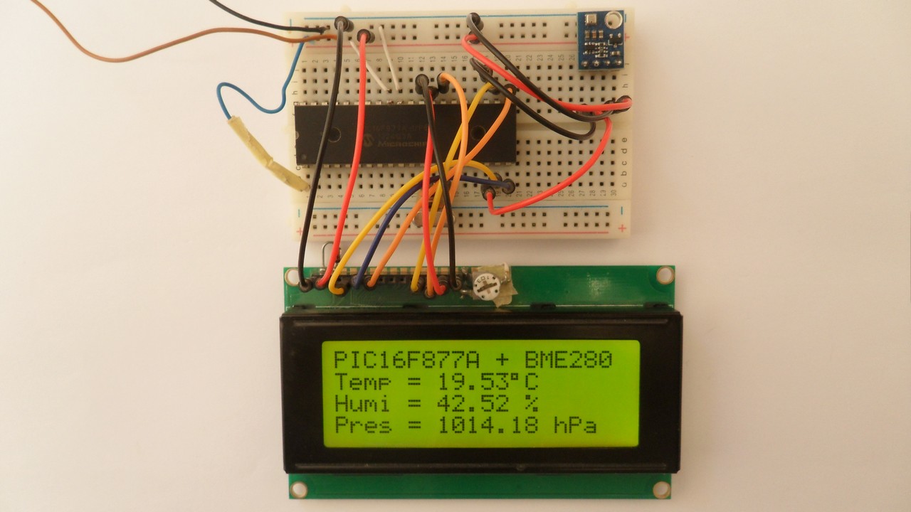
This post shows how to interface Microchip PIC16F877A microcontroller with BME280 barometric pressure, temperature and humidity sensor. Values of temperature, humidity and pressure are displayed on 20×4 LCD screen connected to the microcontroller.
In this project the BME280 sensor is used in I2C mode and the compiler used is CCS PIC C.
The BME280 sensor from Bosch Sensortec is a low cost digital pressure, temperature and humidity sensor with good accuracy. Because pressure changes with altitude we can use it as an altimeter with ±1 meter accuracy (pressure accuracy = ±1 hPa). Some parameters of the sensor are listed below:
Pressure range: 300 … 1100 hPa (equivalent to +9000…-500m above/below sea level)
Pressure resolution: 0.01 hPa ( < 10 cm)
Temperature range: -40 … 85 °C
Temperature resolution: 0.01 °C
Humidity range: 0 … 100 %
Interface: I2C and SPI
Supply voltage range: 1.71 … 3.6 V
The BME280 chip works with maximum voltage of 3.6V (supply voltage range is from 1.71 to 3.6V) which means we’ve to use a 3V3 voltage regulator to supply it from a 5V source.
Also, if we’re working with a 5V system (development board, microcontroller …) like the PIC16F877A microcontroller we’ve to use a voltage level shifter (level converter) which converts the 3.3V (comes from the BME280 chip) into 5V (goes to the PIC16F877A) and vice versa. This level shifter is for the I2C bus lines (clock and data).
Some BME280 modules come with 3V3 voltage regulator and level shifter like the one provided by Adafruit Industries which is shown below.
A module like this can be used with 3.3V or 5V system without any problem.

In this example I’m going to use a Chinese BME280 module came with 3.3V regulator and level shifter, this means connection will be more easier!
BME280 Sensor driver for CCS C compiler:
To simplify the C code, I wrote a simple driver (library) for the BME280 sensor. With this driver the interfacing is more easier.
Driver functions:
BME280_begin(mode, T_sampling, H_sampling, P_sampling, filter, standby): this function initializes the BME280 sensor with the 6 configurations (mode, T_sampling, H_sampling, P_sampling, filter and standby), returns 1 if OK and 0 if error:
mode is sensor mode which can be: MODE_SLEEP, MODE_FORCED or MODE_NORMAL.
T_sampling is temperature oversampling, H_sampling is humidity oversampling and P_sampling is pressure oversampling, each one of them can be one of the following list (library default is SAMPLING_X1):
SAMPLING_SKIPPED —> skipped, output set to 0x80000
SAMPLING_X1 —> oversampling x1
SAMPLING_X2 —> oversampling x2
SAMPLING_X4 —> oversampling x4
SAMPLING_X8 —> oversampling x8
SAMPLING_X16 —> oversampling x16
filter sets BME280 sensor IIR filter configuration, it could be (library default is FILTER_OFF):
FILTER_OFF —> filter off
FILTER_2 —> filter coefficient = 2
FILTER_4 —> filter coefficient = 4
FILTER_8 —> filter coefficient = 8
FILTER_16 —> filter coefficient = 16
standby is BME280 sensor standby time (library default is STANDBY_0_5):
STANDBY_0_5 —> standby time = 0.5 ms
STANDBY_62_5 —> standby time = 62.5 ms
STANDBY_125 —> standby time = 125 ms
STANDBY_250 —> standby time = 250 ms
STANDBY_500 —> standby time = 500 ms
STANDBY_1000 —> standby time = 1000 ms
STANDBY_10 —> standby time = 10 ms
STANDBY_20 —> standby time = 20 ms
Examples:
The following line initializes the BME280 sensor in normal mode, temperature oversampling = X2, humidity oversampling = X1, pressure oversampling = X16, IIR filter coefficient = 16 and standby time = 0.5 ms:
BME280_begin(MODE_NORMAL, SAMPLING_X2, SAMPLING_X1, SAMPLING_X16, FILTER_16, STANDBY_0_5);
and the following line initializes the BME280 sensor in normal mode, temperature oversampling = X1, humidity oversampling = X1, pressure oversampling = X1, IIR filter is off and standby time = 0.5 ms where default settings are used:
BME280_begin(MODE_NORMAL);
BME280_ForcedMeasurement(): this function is used to start a new measurement conversion, used in forced mode only. Returns 1 if ok and 0 if error (sensor is not in sleep mode).
BME280_readTemperature(int32_t temp): reads temperature from BME280 sensor. Temperature is stored in hundredths °C (output value of “5123” equals 51.23 °C). Temperature value is saved to temp, returns 1 if OK and 0 if error.
BME280_readHumidity(uint32_t humi): reads humidity from BME280 sensor. Humidity is stored in relative humidity percent in 1024 steps (output value of “47445” represents 47445/1024 = 46.333 %RH). Humidity value is saved to humi, returns 1 if OK and 0 if error.
BME280_readPressure(uint32_t pres): reads pressure from BME280 sensor. Pressure is stored in Pa (output value of “96386” equals 96386 Pa = 963.86 hPa). Pressure value is saved to pres, returns 1 if OK and 0 if error.
BME280 driver for CCS C compiler download:
Driver source file download link is below, installation of this driver is easy, just add it to project folder or CCS C drivers folder (for example C:\Program Files (x86)\CCS\Drivers). Driver name is: BME280_Lib.c.
BME280 CCS C driver
Interfacing PIC16F877A microcontroller with BME280 sensor:
Hardware Required:
- PIC16F877A microcontroller —> datasheet
- BME280 sensor module with 3.3V regulator and level shifter —-> BME280 datasheet
- 2004 LCD screen
- 8 MHz crystal oscillator
- 2 x 22pF ceramic capacitor
- 10k ohm variable resistor (or potentiometer)
- 330 ohm resistor
- 10k ohm resistor
- 5V source
- Breadboard
- Jumper wires
- PIC Microcontroller programmer (PICkit 3, PICkit 4…)
Example circuit schematic diagram is shown below.
Note that the BME280 module shown in the circuit diagram has a 3.3V regulator and level shifter.

Generally, the BME280 module has at least 4 pins because it can work in SPI mode or I2C mode. For the I2C mode we need 4 pins: VCC, GND, SCL and SDA where:
GND (ground) is connected to circuit ground (0V)
VCC is the supply pin, it is connected to +5V
SCL is I2C bus serial clock line, connected to PIC16F877A RC3 pin (#18)
SDA is I2C bus serial data line, connected to PIC16F877A RC4 pin (#23).
The 20×4 LCD screen is used to display temperature, humidity and pressure values where:
RS —> pin RD0
RW —> pin RD1
E —> pin RD2
D4 —> pin RD3
D5 —> pin RD4
D6 —> pin RD5
D7 —> pin RD6
VSS, D0, D1, D2, D3 and K are connected to circuit ground
VEE to the variable resistor (or potentiometer) output
VDD to +5V and A to +5V through 330 ohm resistor.
VEE pin is used to control the contrast of the LCD. A (anode) and K (cathode) are the back light LED pins.
In this project the PIC16F877A microcontroller runs with 8 MHz crystal oscillator.
Interfacing PIC16F877A with BME280 sensor C code:
The C code below is for CCS C compiler, it was tested with version 5.051.
To be able to compile project C code, a driver for the BME280 sensor is required, download link is above.
After you download the driver file which named BME280_Lib.c, add it to your project folder!
As any other I2C device, the BME280 sensor has an I2C slave address which is 0xEC or 0xEE. This address depends on the connection of the SDO pin (used for SPI mode as serial data out or MISO), if the SDO pin is connected (directly or through resistor) to VCC (3.3V) the address will be 0xEE, and if it’s connected to GND the address will be 0xEC.
The default I2C address of the library is defined as 0xEE and my device I2C address is 0xEC.
In the code the definition of the I2C slave address is as shown below:
1 2 | // define device I2C address: 0xEC or 0xEE (0xEE is library default address) #define BME280_I2C_ADDRESS 0xEC |
The initialization of the BME280 sensor is done using the function BME280_begin(MODE_NORMAL) which returns 1 if OK and 0 if error. In the code the initialization of the sensor is as shown below:
1 2 3 4 5 6 7 | // initialize the BME280 sensor if(BME280_begin(MODE_NORMAL) == 0) { // connection error or device address wrong! lcd_gotoxy(2, 2); // go to column 1 row 1 lcd_putc("Connection error!"); while(TRUE); // stay here } |
The LCD displays “connection error!” if there was an error with the initialization of the device.
Reading the values of temperature, humidity and pressure is done as shown below.
Note that the library returns the temperature in hundredths °C which means we’ve to divide it by 100, it returns the humidity in relative humidity percent (RH%) in 1024 steps which means we’ve to divide it by 1024 and it returns the pressure in Pa, to get the pressure in hPa we’ve to divide it by 100.
1 2 3 4 5 | // Read temperature (in hundredths C), pressure (in Pa) // and humidity (in 1024 steps RH%) values from BME280 sensor BME280_readTemperature(&temperature); // read temperature BME280_readHumidity(&humidity); // read humidity BME280_readPressure(&pressure); // read pressure |
Temperature, humidity and pressure values are displayed on 20×4 LCD screen.
1 bar = 10000 Pa = 100 hPa. ( 1 hPa = 100 Pa)
Pa: Pascal
hPa: hectoPascal
Full CCS C Code:
1 2 3 4 5 6 7 8 9 10 11 12 13 14 15 16 17 18 19 20 21 22 23 24 25 26 27 28 29 30 31 32 33 34 35 36 37 38 39 40 41 42 43 44 45 46 47 48 49 50 51 52 53 54 55 56 57 58 59 60 61 62 63 64 65 66 67 68 69 70 71 72 73 74 75 76 77 78 79 80 81 82 83 84 85 86 87 88 89 90 | /* * Interfacing PIC16F877A microcontroller with BME280 temperature, humidity * and pressure sensor. * C Code for CCS C compiler. * Temperature, humidity and pressure values are displayed on 20x4 LCD. * This is a free software with NO WARRANTY. * http://simple-circuit.com/ */ // define device I2C address: 0xEC or 0xEE (0xEE is library default address) #define BME280_I2C_ADDRESS 0xEC // LCD module connections #define LCD_RS_PIN PIN_D0 #define LCD_RW_PIN PIN_D1 #define LCD_ENABLE_PIN PIN_D2 #define LCD_DATA4 PIN_D3 #define LCD_DATA5 PIN_D4 #define LCD_DATA6 PIN_D5 #define LCD_DATA7 PIN_D6 // end LCD module connections #include <16F877A.h> #fuses HS, NOWDT, NOPROTECT, NOLVP #use delay(clock = 8MHz) #use I2C(MASTER, I2C1, FAST = 400000, STREAM = BME280_STREAM) #include <BME280_Lib.c> // include BME280 sensor driver source file #include <lcd.c> // include LCD driver source file signed int32 temperature; unsigned int32 pressure, humidity; void main() { delay_ms(1000); // wait 1 second lcd_init(); // initialize LCD module lcd_putc('\f'); // clear the LCD lcd_gotoxy(1, 1); // go to column 1 row 1 lcd_putc("PIC16F877A + BME280"); // initialize the BME280 sensor if(BME280_begin(MODE_NORMAL) == 0) { // connection error or device address wrong! lcd_gotoxy(2, 2); // go to column 2 row 2 lcd_putc("Connection error!"); while(TRUE); // stay here } lcd_gotoxy(1, 2); // go to column 1 row 2 lcd_putc("Temp ="); lcd_gotoxy(21, 1); // go to column 1 row 3 lcd_putc("Humi ="); lcd_gotoxy(21, 2); // go to column 1 row 4 lcd_putc("Pres ="); while(TRUE) { // Read temperature (in hundredths C), pressure (in Pa) // and humidity (in 1024 steps RH%) values from BME280 sensor BME280_readTemperature(&temperature); // read temperature BME280_readHumidity(&humidity); // read humidity BME280_readPressure(&pressure); // read pressure // print data on the LCD screen // 1: print temperature lcd_gotoxy(7, 2); // go to column 7 row 2 if(temperature < 0) { // if temperature is negative lcd_putc('-'); // print minus sign temperature = abs(temperature); // abs: absolute value } else lcd_putc(' '); printf(lcd_putc, "%02Lu.%02Lu%cC", temperature / 100, temperature % 100, 223); // 2: print humidity lcd_gotoxy(28, 1); // go to column 8 row 3 printf(lcd_putc, "%02Lu.%02Lu %%", humidity / 1024, ((humidity * 100)/1024) % 100); // 3: print pressure lcd_gotoxy(28, 2); // go to column 8 row 4 printf(lcd_putc, "%04Lu.%02Lu hPa", pressure/100, pressure % 100); delay_ms(2000); // wait 2 seconds } } // end of code. |
Related Project:
Interfacing PIC MCU with BMP280 temperature and pressure sensor
Discover more from Simple Circuit
Subscribe to get the latest posts sent to your email.

I have get BME280 device from Aliexpress.
The temperature and air pressure works well, but not humidity
The reason is the different BME280_CHIP_ID, it should be 0x60, but I have 0xD0,
I had tied to change it, but no help.
The I2C address is a normal 0xEE.
The device name is GY /BMP/E280.
Do you have any idea where I can find a new library or how to change this ?
I have real CCS library, but this doesn’t work either .
It is a quite old, maybe somebody must made a new.
The 0xD0 is the address where device’s chip ID is stored, for both BMP280 and BME280. The BMP280 has a chip ID = 0x58, and the BME280 device ID = 0x60.
In Aliexpress the GY-/BMP/E280 module may come with BMP280 or BME280, if you already purchased the BMP280 sensor then you will get temperature & pressure readings, and if you have BME280 sensor then you should get temperature & pressure & humidity readings.
Both libraries (BMP280_Lib.c and BME280_Lib.c) check device’s ID while initializing the sensor (using bmp280_begin or bme280_begin function), if it does not match with the correct chip ID then the function will return 0.
As a result, if you’re using the BMP280_Lib.c and you successfully get a correct temperature & pressure readings then you have the BMP280 sensor not the BME280. You have to be sure which device you’re working with.
Thanks for nice reply.
I think that my device is BME280. It says GY-/BMP/E280.
I found your BME280_LIB.c library and used my address BME280_I2C_ADDRESS 0xEC,
It was not 0x58 or 0x60.
I checked it with I2C scanner.
However it was not right.
Here is my new program results:
Probyte BME280 sender,LDR,NTC 10-Sep-23
Connection error!
Forced 1
BME280 sender 10-Sep-23
Probyte BME280 sender,LDR,NTC 10-Sep-23
102400#TT15+24.38,-10.63,084,0848.60,100.00$
102400#TT15+24.42,-10.63,084,0848.60,100.00$
==
The first number is Humidity response.
The second number +24.38 C was my NTC temperature, which was right.
The third number was BME280 temperature, it was wrong.
The four number was LCD, which was right.
The fifth number was 0848.60, which was wrong. It should be about 100,1 mBar.
The six number was 100.00, which should be about 55- 65%
==
My sensor can know temp, pressure, but not humidity.
How my I2C scanner gives 0xEC, but I got the error with BME280_lib.c, but BMP280 gives right answer
when I use BMP280_LIB.c?
Regards Pekka
You are mixing between I2C address and sensor chip ID, you’ve to understand that the CHIP ID comes with the device manufacturer and we can not change it, the CHIP ID value for the BMP280 sensor is 0x58 and for the BME sensor the CHIP ID is 0x60.
The I2C address of your device regardless if it is BMP280 or BME280 is 0xEC. I2C Scanner checks the I2C address not the chip ID of the device.
If you are currently using the BME280__Lib.c , please check whether the function BME280_begin returns 1 or 0, if it returns 0 then you are using the BMP280 sensor and if it returns 1 then you are using the BME280 sensor. You can write a simple code to check that return, for example connect an LED to a pin RB0 and use this code, if the LED lights up then you have the BMP280 sensor:
output_low(PIN_B0);
if(BME280_begin(MODE_NORMAL) == 0)
{ // connection error or device address wrong!
output_high(PIN_B0);
while(TRUE); // stay here
}
OK, I have try, when I got my device from garage.
I wonder why the temperature and air pressure works perfectly with other library.
It is BMP280_lib.c, but it doesn’t have a humidity. Is my GY BME/ BM280 the wrong version?
Here is the picture of my device
Regards Pekka
According to your photo it is BME280, it looks it is just a photo from the internet!
If you can give a another clear photo of your real device that you are working with, so we can check if it is BMP280 or BME280. Please take a clear photo of your device (not from the internet) and give us the link after you upload it.
Am I missing something or is BME280_STREAM not actually defined anywhere?
here is the real photo
This answer goes to wrong person
Pekka
The link does not work, please check!
Here is again wrong reply to Eric.
This a new picture
Pekka
Please I mean the front side of the PCB where the sensor itself is place, a PCB with no component is useless!
Well, I doesn’t understand.
Do you mean the PCB with sensor.
Is this just what you wanted?
What do you mean?
It has six holes, but I have used only four holes.
VCC, Gnd, and two I2C wires with 1.7k ohm resistors to 3.3V
Pekka
I mean the other side of the sensor module, de-solder your sensor module from the main board and take a clear photo of the side where the sensor itself is located, the same as your first photo (upper photo):
The hook up diagram is incorrect make sure that pin SDO is connected to ground and the the address is 0xEC fro the I2C mode. The diagram shows the SDO pin floating. Also then you must change the define code in the BME280_lib file to this #define BME280_I2C_ADDRESS 0xEC
Jim
Circuit diagram shows only 4 pins for the BME280 sensor module: SDA, SCL, GND and VCC. SDO pin is not shown at all and its connection is inside the module.
For the I2C address, device datasheet does say that the I2C interface uses 3 pins:
SCK: serial clock (SCL),
SDI: data (SDA),
SDO: Slave address LSB (GND = ‘0’, VDDIO= ‘1’).
Device slave address is: 111011X0 (‘X’ is determined by state of SDO pin). That means if SDO is connected to GND then the address is: 11101100 = 0xEC, and if it’s connected to VDDIO then the address becomes: 11101110 = 0xEE.
Reference: BME280 datasheet, page 33/55.
Jim. I connect SDO to ground, but I got lots of errors.
I have done some additional printf(“xx”), files to library
Probyte BME280 sender,LDR,NTC 12-Sep-23
Regards Pekka Ritamaki
Hey, I was working with CCS support form yesterday.
I was using BME280.c library from CCS.
I modified my code to slower and slower whole day, when it game a night.
I was trying to put SDO to ground and open.
It doesn’t works
Today I loaded the old simple-circuit BMP280_lib.c and it works.
I has SDO connected to ground and before it was open. I doesn’t mean anything.
I my AliExpress device BMP280 and not BME280?
I do not care any more. You have excellent library!
This morning weather
Pekka Ritamaki
Since you are getting temperature & pressure readings correctly and you’re not able to get the humidity one, then your sensor is the BMP280.
To get all the three reading you have to buy a real BME280 sensor and you must be sure that you have the right sensor, and use the BME280_Lib.c library to correctly read all the three parameters (temperature, pressure & humidity).
I have set of library for BME280 (I2C, calculate T,P,H e.t.c ) as .ASM and .INC modules. Full projekt (LCD 1602 I2c interface + BME280 + MCU PIC) properly work on (ATTENTION!!!!) PIC12F683
Hi Alex, already more than a year ago but could you share your code with me?
hello, thanks for the nice project as always.
is there an operational proteus vsm part for the bme280?
I think until now there is no Proteus model for the BME280 sensor.
Hi, Can I see your I2C code?
If you mean I2C library source code, it’s a built-in function (library) that comes with CCS C compiler and “I think” there’s no way to see its source code!