This post shows how to interface Arduino UNO board with DHT11 (RHT01) digital humidity and temperature sensor.
The Arduino reads temperature (in °C) & humidity (in rH%) values from the DHT11 sensor and print their values on ST7789 TFT display.
The ST7789 TFT module contains a display controller with the same name: ST7789. It’s a color display that uses SPI interface protocol and requires 3, 4 or 5 control pins, it’s low cost and easy to use. This display is an IPS display, it comes in different sizes (1.3″, 1.54″ …) but all of them should have the same resolution of 240×240 pixel, this means it has 57600 pixels. This module works with 3.3V only and it doesn’t support 5V (not 5V tolerant).
TFT: Thin-Film Transistor.
SPI: Serial Peripheral Interface.
IPS: In-Plane Switching.
To see how to interface Arduino with ST7789 TFT display, visit this post:
Interfacing Arduino with ST7789 TFT Display – Graphics Test Example
About DHT11 sensor:
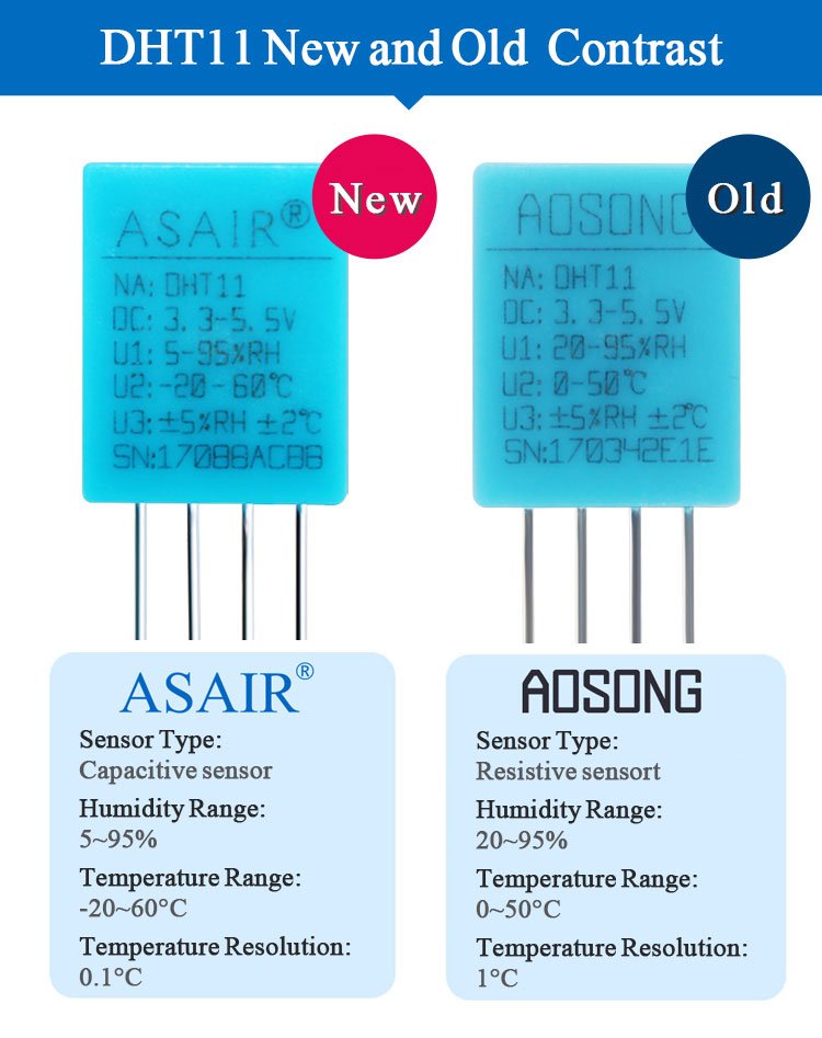
There are two types of the DHT11 sensor: old type (AOSONG) and new type (ASAIR). The differences between the 2 types are summarized below:
Seeed Studio provides a good module of the new DHT11 sensor (ASAIR version) named “Grove Temperature & Humidity Sensor”, more details in its official page:
Grove Temperature & Humidity Sensor
Hardware Required:
- Arduino board
- ST7789 TFT display module (1.3″, 1.54″ …)
- DHT11 (RHT01) humidity and temperature sensor —-> datasheet
- 4 x 3.3k ohm resistor (+1 if the display module has CS pin)
- 4 x 2.2k ohm resistor (+1 if the display module has CS pin)
- 4.7k ohm resistor
- Breadboard
- Jumper wires
Arduino with DHT11 sensor and ST7789 TFT display circuit:
The image below shows project circuit diagram.
The DHT11 sensor has 4 pins (from left to right):
Pin 1 is power supply pin, connected to Arduino 5V pin,
Pin 2: data output pin, connected to Arduino analog pin 2 (A2),
Pin 3: not connected pin,
Pin 4: GND (ground), connected to Arduino GND pin.
A pull-up resistor of 4.7k ohm is required because the DHT11 sensor has an open drain output.
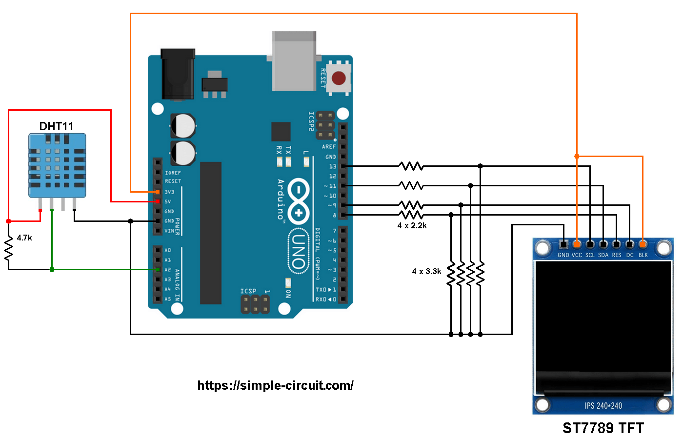
The ST7789 display module shown in project circuit diagram has 7 pins: (from right to left): GND (ground), VCC, SCL (serial clock), SDA (serial data), RES (reset), DC (or D/C: data/command) and BLK (back light).
Connecting the BLK pin is optional. The back light turns off when the BLK pin connected to the ground (GND).
As mentioned above, the ST7789 TFT display controller works with 3.3V only (power supply and control lines). The display module is supplied with 3.3V (between VCC and GND) which comes from the Arduino board.
All Arduino UNO board output pins are 5V, connecting a 5V pin to the ST7789 TFT display may damage its controller.
To connect the Arduino to the display module, I used voltage divider for each line which means there are 4 voltage dividers. Each voltage divider consists of 2.2k and 3.3k resistors, this drops the 5V into 3V which is sufficient.
If the display module has a CS pin (Chip Select) then it should be connected to Arduino digital pin 10 through another voltage divider.
So, the ST7789 TFT display is connected to the Arduino board as follows (each one through voltage divider):
RST pin is connected to Arduino digital pin 8,
DC pin is connected to Arduino digital pin 9,
SDA pin is connected to Arduino digital pin 11,
SCL pin is connected to Arduino digital pin 13.
Other pins are connected as follows:
VCC pin is connected to Arduino 3V3 pin,
GND pin is connected to Arduino GND pin,
BL (LED) pin is connected to Arduino 3V3 pin (optional).
Arduino with DHT11 sensor and ST7789 TFT display code:
The following Arduino code requires 3 libraries from Adafruit Industries:
The first library is a driver for the ST7789 TFT display which can be installed from Arduino IDE library manager (Sketch —> Include Library —> Manage Libraries …, in the search box write “st7789” and install the one from Adafruit).
The second library is Adafruit graphics library which can be installed also from Arduino IDE library manager.
The 3rd library is for the DHT11 sensor, it may be installed using library manager (in the search box write “dht” and choose the one from Adafruit).
The 3 libraries can be installed manually, first download them from the following 3 links:
Adafruit ST7789 TFT library —-> direct link
Adafruit graphics library —-> direct link
Adafruit DHT library —-> direct link
After the download, go to Arduino IDE —> Sketch —> Include Library —> Add .ZIP Library … and browse for the .zip file (previously downloaded).
The same thing for other library files.
Hints:
The 3 libraries are included in the main code as follows:
1 2 3 | #include <Adafruit_GFX.h> // Adafruit core graphics library #include <Adafruit_ST7789.h> // Adafruit hardware-specific library for ST7789 #include <DHT.h> // Adafruit DHT library code |
The ST7789 TFT module pins (CS, RST and DC) connections are defined as shown below (even the display module has no CS pin but its definition is required by the Adafruit ST7789 library):
1 2 3 4 | // ST7789 TFT module connections #define TFT_CS 10 // define chip select pin #define TFT_DC 9 // define data/command pin #define TFT_RST 8 // define reset pin, or set to -1 and connect to Arduino RESET pin |
The other display pins (SDA and SCL) are connected to Arduino hardware SPI module pins (digital pin 11 and digital pin 13 respectively for MOSI and SCLK).
The Adafruit ST7789 library is initialized with this line:
1 | Adafruit_ST7789 tft = Adafruit_ST7789(TFT_CS, TFT_DC, TFT_RST); |
And the TFT display is initialized using the following command:
1 2 3 | // initialize the ST7789 display (240x240 pixel) // if the display has CS pin try with SPI_MODE0 tft.init(240, 240, SPI_MODE2); |
Definition of sensor type, its data pin connection and the initialization of the DHT library:
1 2 3 | #define DHTPIN A2 // DHT11 data pin is connected to Arduino analog pin 2 #define DHTTYPE DHT11 // DHT11 sensor is used DHT dht11(DHTPIN, DHTTYPE); // initialize DHT library |
Rest of code is described through comments.
Full Arduino code:
1 2 3 4 5 6 7 8 9 10 11 12 13 14 15 16 17 18 19 20 21 22 23 24 25 26 27 28 29 30 31 32 33 34 35 36 37 38 39 40 41 42 43 44 45 46 47 48 49 50 51 52 53 54 55 56 57 58 59 60 61 62 63 64 65 66 67 68 69 70 71 72 73 74 75 76 77 78 79 80 81 82 83 84 85 | /*********************************************************************** * * Interfacing Arduino with ST7789 TFT display (240x240 pixel) * and DHT11 digital humidity & temperature sensor. * This is a free software with NO WARRANTY. * http://simple-circuit.com/ * ***********************************************************************/ #include <Adafruit_GFX.h> // Adafruit core graphics library #include <Adafruit_ST7789.h> // Adafruit hardware-specific library for ST7789 #include <DHT.h> // Adafruit DHT library code // ST7789 TFT module connections #define TFT_CS 10 // define chip select pin #define TFT_DC 9 // define data/command pin #define TFT_RST 8 // define reset pin, or set to -1 and connect to Arduino RESET pin // initialize Adafruit ST7789 TFT library with hardware SPI module // MOSI(SDA) ---> Arduino digital pin 11 // SCK (SCL) ---> Arduino digital pin 13 Adafruit_ST7789 tft = Adafruit_ST7789(TFT_CS, TFT_DC, TFT_RST); #define DHTPIN A2 // DHT11 data pin is connected to Arduino analog pin 2 #define DHTTYPE DHT11 // DHT11 sensor is used DHT dht11(DHTPIN, DHTTYPE); // initialize DHT library void setup(void) { // initialize the ST7789 display (240x240 pixel) // if the display has CS pin try with SPI_MODE0 tft.init(240, 240, SPI_MODE2); // if the screen is flipped, remove this command tft.setRotation(2); // fill the screen with black color tft.fillScreen(ST77XX_BLACK); tft.setTextWrap(false); // turn off text wrap option tft.setTextColor(ST77XX_GREEN, ST77XX_BLACK); // set text color to green and black background tft.setTextSize(3); // text size = 3 tft.setCursor(15, 40); // move cursor to position (15, 27) pixel tft.print("TEMPERATURE:"); tft.setTextColor(ST77XX_YELLOW, ST77XX_BLACK); // set text color to yellow and black background tft.setCursor(43, 140); // move cursor to position (15, 27) pixel tft.print("HUMIDITY:"); tft.setTextSize(4); // text size = 4 // initialize DHT11 sensor dht11.begin(); } char _buffer[7]; // main loop void loop() { delay(1000); // wait a second // read humidity in rH% int Humi = dht11.readHumidity() * 10; // read temperature in degrees Celsius int Temp = dht11.readTemperature() * 10; // print temperature (in °C) tft.setTextColor(ST77XX_RED, ST77XX_BLACK); // set text color to red with black background if(Temp < 0) // if temperature < 0 sprintf(_buffer, "-%02u.%1u", (abs(Temp)/10)%100, abs(Temp) % 10); else // temperature >= 0 sprintf(_buffer, " %02u.%1u", (Temp/10)%100, Temp % 10); tft.setCursor(26, 71); tft.print(_buffer); tft.drawCircle(161, 77, 4, ST77XX_RED); // print degree symbol ( ° ) tft.drawCircle(161, 77, 5, ST77XX_RED); tft.setCursor(170, 71); tft.print("C"); // print humidity (in %) tft.setTextColor(ST77XX_CYAN, ST77XX_BLACK); // set text color to cyan and black background sprintf(_buffer, "%02u.%1u %%", (Humi/10)%100, Humi % 10); tft.setCursor(50, 171); tft.print(_buffer); } // end of code. |

Related Project:
Interfacing Arduino with ST7789 TFT and DHT22 Sensor
Discover more from Simple Circuit
Subscribe to get the latest posts sent to your email.


Thanks friend,
i am new to Arduino and really happy you all reply immediately.
really works after update. its miracle
one program working on old file another working in new one. now i tested both program after update working fine
by reply from below link
http://simple-circuit.com/arduino-st7789-ips-tft-display-example/
hi i am using display which was purchased from aliexpress . after made change in SPI_MODE0 TO 3 display works with the program copied from following link
http://simple-circuit.com/arduino-st7789-ips-tft-display-example/
now i used this project, uploaded with modification of spi mode display works but texts are mirrored and not displayed with in the display range (out of display area)
then i tried to modify the setrotation(0) setrotation(2) setrotation(3) not working even i removed the setrotation(0) function.
when setting to setrotation(1) text displayed inside display area bu landscape and mirrored
when using above link program i faced one problem is while removing all content like draw lines, circle, et display works well but while removing testroundrectangle function the display works only half part. so i used draw round rectangle as welcome screen
i am struggling with display for long time in starting colour issue cam after modifying the spimode to 3 inside driver files colours came
looking for help
thanks in advance