This Arduino project shows how to build a digital voltmeter which can measure up to 600V. This voltmeter can measure AC and DC voltages with automatic switching between the 2 signals, it also can automatically switch between measuring ranges (autoranging).
This Arduino based voltmeter measures the TRMS (true RMS) value of AC voltage signals and calculates its frequency.
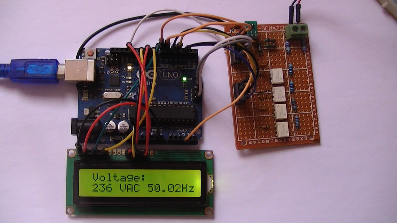
A 1602 LCD screen is used to display voltage value, signal type (AC or DC) and frequency (if signal is AC).
Hints:
No warranty is provided with this project, so do it at your own risk!
No isolation transformer is used between the Arduino board and mains source, please don’t connect the Arduino to your laptop or PC while you’re measuring voltages.
While measuring mains voltage (the Arduino is connected to the mains), there will be a very small current (less than 0.4 mA) that may pass through the Arduino. Even this current is so small which may not harm human body and for safety purpose, please don’t touch the Arduino while you’re measuring mains voltage!
For more safety and better results, the Arduino board should be powered from battery (for example battery of 9 Volts).
AC: Alternating Current.
DC: Direct Current.
TRMS: True Root Mean Square.
Hardware Required:
- Arduino UNO board —-> Atmega328P datasheet
- 16×2 LCD screen
- 330 ohms resistor
- 10k ohms variable resistor or potentiometer
- 4 x MOC3020 optocoupler (MOC3021, MOC3022, MOC3023, or equivalent) —-> datasheet
- 4 x 220 ohm resistor
- LM4040 – 4.1V (4.096V shunt voltage reference) —-> datasheet
- 100 nF capacitor
- 2 x 0.1 nF capacitor
- 2 x 1M (Mega) ohms resistor with 1% tolerance or better
- 220k ohms resistor with 1% tolerance or better
- 15k ohms resistor with 1% tolerance or better
- 2 x 4.7k ohms resistor with 1% tolerance or better
- 4 x 10k ohms resistor with 1% tolerance or better
- 1k ohms resistor
- Breadboard
- Jumper wires
Arduino Autoranging AC/DC Voltmeter Circuit:
Project circuit diagram is shown below.
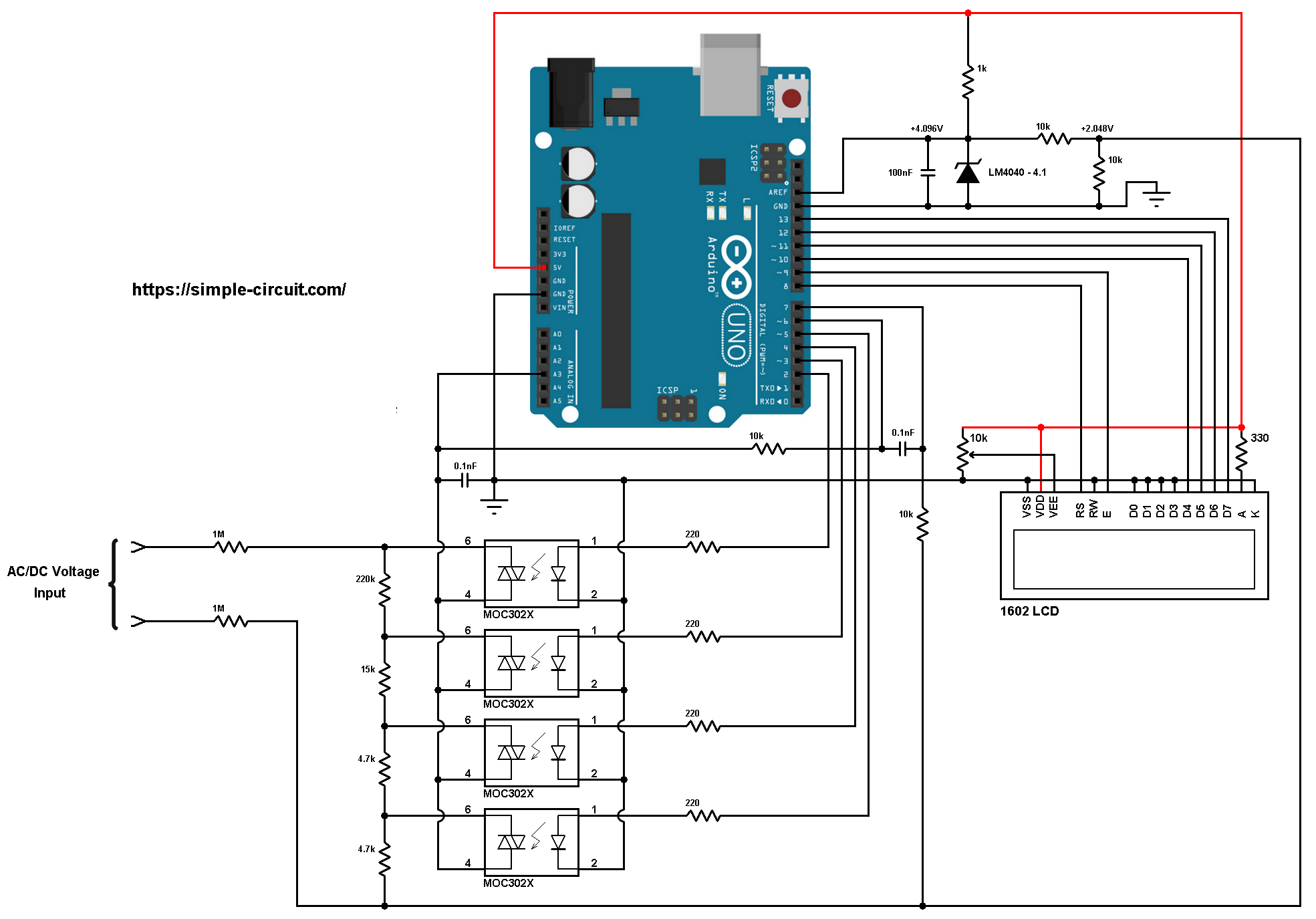
Grounded terminals should be externally connected together!
Basically, a voltage of more than 5 Volts can not be directly connected to the Arduino UNO board. To do that we need a step down circuit which downs any input voltage to another one lower than 5V. For an AC voltage we can use a step down transformer, but measurements will not be accurate!
In this project I used voltage divider circuit which consists of 6 resistors as shown in the circuit schematic above (for better results resistors tolerance should be of 1% or lower).
The total resistance of the voltage divider is: 2M + 220k + 15k + 4.7k + 4.7k = 2244.4k Ohms.
For the autoranging purpose I used 4 optoisolators (MOC3020 or equivalent) with triac in one side, this allows current to flow in either directions when the optoisolator LED is triggered.
As shown in the circuit diagram, pin number 4 of each optoisolator (optocoupler) is connected to Arduino analog channel 3 (A3), pin number 6 of each opto-isolator is connected to 1 voltage divider output.
For example, the upper opto-isolator shown in the circuit diagram is connected to largest second resistance of the voltage divider which is equal to: 220k + 15k + 4.7k + 4.7k = 244.4k Ohms. So, voltage divider ration equals to: 2244.4/244.4 = 9.183.
The LM4040-4.1 shunt voltage reference has 2 roles: the fist one is to provide a precise voltage of 4.096V which is then connected to pin AREF of the Arduino board. This voltage is used as positive reference of the ADC module, the negative reference is GND (0V).
The 2nd role is to provide a precise DC bias of 2.048V to the input signal (voltage under measure) which prevents the voltage on Arduino analog channel 3 from going under 0V (negative voltage).
The ATmega328P microcontroller has 2 internal clamping diodes on the I/O pins, these diodes are connected from the I/O pin to VCC and GND and they keep all input signals within the operating voltage (-0.5V to VCC + 0.5V). Any voltage higher than VCC + 0.5V will be forced down to VCC + 0.5V and any voltage below GND – 0.5V will be forced up to GND – 0.5V.
As a result, connecting 2-phase voltage of 400V RMS to the above circuit will not do any damage to the ATmega328P microcontroller, even when the voltage divider with lowest ration is selected.
Arduino digital pin 6 is also connected to the common pin of the optoisolators through 10k resistor. Arduino digital pin 7 is connected to +2.048V point through 10k resistor.
Arduino digital pins 6 and 7 are ATmega328P analog comparator inputs (respectively AIN0 and AIN1). The analog comparator is used to detect whether the voltage signal is AC or DC and also for counting AC voltage frequency.
The 16×2 LCD screen (2 rows and 16 columns) is used to display the value of the input voltage, signal type (AC or DC) and AC voltage frequency value, it’s connected to the Arduino board as follows:
RS —> Arduino digital pin 8
E —> Arduino digital pin 9
D4 —> Arduino digital pin 10
D5 —> Arduino digital pin 11
D6 —> Arduino digital pin 12
D7 —> Arduino digital pin 13
VSS, RW, D0, D1, D2, D3 and K are connected to Arduino GND,
VEE to the 10k Ohms variable resistor (or potentiometer) output,
VDD to Arduino 5V and A to Arduino 5V through 330 ohm resistor.
VEE pin is used to control the contrast of the LCD. A (anode) and K (cathode) are the back light LED pins.
Arduino Autoranging AC/DC Voltmeter Code:
The following Arduino code can measure TRMS value of AC voltages with its corresponding frequency.
Voltage type (AC or DC) is automatically detected, and range is automatically selected (4 ranges).
1 2 3 4 5 6 7 8 9 10 11 12 13 14 15 16 17 18 19 20 21 22 23 24 25 26 27 28 29 30 31 32 33 34 35 36 37 38 39 40 41 42 43 44 45 46 47 48 49 50 51 52 53 54 55 56 57 58 59 60 61 62 63 64 65 66 67 68 69 70 71 72 73 74 75 76 77 78 79 80 81 82 83 84 85 86 87 88 89 90 91 92 93 94 95 96 97 98 99 100 101 102 103 104 105 106 107 108 109 110 111 112 113 114 115 116 117 118 119 120 121 122 123 124 125 126 127 128 129 130 131 132 133 134 135 136 137 138 139 140 141 142 143 144 145 146 147 148 149 150 151 152 153 154 155 156 157 158 159 160 161 162 163 164 165 166 167 168 169 170 171 172 173 174 175 176 177 178 179 180 181 182 183 184 185 186 187 188 189 190 191 | /************************************************************************** * * Arduino autoranging AC/DC voltmeter. * Voltage and frequency are printed on 1602 LCD screen. * This is a free software with NO WARRANTY - Use it at your own risk! * https://simple-circuit.com/ * *************************************************************************/ #include <LiquidCrystal.h> // include Arduino LCD library // LCD module connections (RS, E, D4, D5, D6, D7) LiquidCrystal lcd(8, 9, 10, 11, 12, 13); // define autoranging channel pins #define CH0 2 #define CH1 3 #define CH2 4 #define CH3 5 const uint16_t Time_Out = 50000, // time out in microseconds Periods = 10; // number of periods of measurement (for AC voltage only) // variables byte ch_number; const uint16_t res_table[4] = {2444, 244, 94, 47}, // voltage divider resistances in tenths kOhms total_res = 22444; // total resistance in tenths kOhms uint16_t current_res; volatile byte per; void setup(void) { pinMode(CH0, OUTPUT); pinMode(CH1, OUTPUT); pinMode(CH2, OUTPUT); pinMode(CH3, OUTPUT); lcd.begin(16, 2); // set up the LCD's number of columns and rows lcd.setCursor(1, 0); lcd.print("Voltage:"); ch_number = 0; ch_select(ch_number); // ADC and analog comparator configuration ADMUX = 0x03; ADCSRA = 0x87; ADCSRB = (0 << ACME); // select AIN1 as comparator negative input ACSR = 0x13; // turn on analog comparator } // analog comparator ISR ISR (ANALOG_COMP_vect) { byte count = 0; for(byte i = 0; i < 50; i++) { if ( ACSR & 0x20 ) count++; } if(count > 48) per++; } // main loop void loop() { bool dc_flag = 0; // DC voltage flag bit int32_t sum = 0; // sum of all readings uint16_t n = 0; // number of readings (samples) ACSR = (1 << ACI); // clear analog comparator interrupt flag ACSR = (1 << ACIE); // enable analog comparator interrupt uint32_t current_m = micros(); // save current millis byte current_per = per; // save current period number while ( (current_per == per) && (micros() - current_m < Time_Out) ) ; if( micros() - current_m >= Time_Out ) { // if there's time out event ==> voltage signal is DC dc_flag = 1; for (byte i = 0; i < 200; i++) { ADCSRA |= 1 << ADSC; // start conversion while(ADCSRA & 0x40); // wait for conversion complete int16_t an = (int16_t)(ADCL | (uint16_t)ADCH << 8) - 511; sum += an; n++; // increment number of readings delay(1); } } else { // here, voltage signal is AC current_m = micros(); // save current millis() per = 0; while ( (per < Periods) && (micros() - current_m < (uint32_t)Time_Out * Periods) ) { ADCSRA |= 1 << ADSC; // start conversion while(ADCSRA & 0x40); // wait for conversion complete int32_t an = (int16_t)(ADCL | (uint16_t)ADCH << 8) - 511; sum += sq(an); // sq: square n++; // increment number of readings } } ACSR = (0 << ACIE); // disable analog comparator interrupt uint32_t total_time = micros() - current_m; // used to claculate frequency // voltage calculation float v; if(dc_flag) // if voltage signal is DC v = (4 * sum)/n; // calculate Arduino analog channel DC voltage in milli-Volts else // here voltage signal is AC v = 4 * sqrt(sum/n); // calculate Arduino analog channel RMS voltage in milli-Volts // claculate actual (input) voltage in milli-Volts (apply voltage divider equation) v = v * (float)total_res/current_res; v /= 1000; // get voltage in Volts uint16_t v_abs = abs(int16_t(v)); if( (v_abs >= 10 && ch_number == 0) || (v_abs >= 100 && ch_number == 1) || (v_abs >= 250 && ch_number == 2) ) { ch_number++; ch_select(ch_number); delay(10); return; } if( (v_abs < 220 && ch_number == 3) || (v_abs < 80 && ch_number == 2) || (v_abs < 8 && ch_number == 1) ) { ch_number--; ch_select(ch_number); delay(10); return; } char _buffer[8]; lcd.setCursor(0, 1); if( v < 0) lcd.print('-'); else lcd.print(' '); if(v_abs < 10) sprintf( _buffer, "%01u.%02u", v_abs, abs((int16_t)(v * 100)) % 100 ); else if( v_abs < 100) sprintf( _buffer, "%02u.%01u", v_abs, abs((int16_t)(v * 10)) % 10 ); else sprintf( _buffer, "%03u ", v_abs ); lcd.print(_buffer); if(dc_flag) lcd.print("VDC "); else { lcd.print("VAC "); // calculate signal frequency in Hz uint32_t period_time = total_time/Periods; float freq = 1000000.0/period_time; sprintf( _buffer, "%02u.%02uHz", (uint16_t)freq % 100, (uint16_t)(freq * 100) % 100 ); lcd.print(_buffer); } delay(500); // wait half a second } void ch_select(byte n) { switch(n) { case 0: digitalWrite(CH0, HIGH); digitalWrite(CH1, LOW); digitalWrite(CH2, LOW); digitalWrite(CH3, LOW); break; case 1: digitalWrite(CH0, LOW); digitalWrite(CH1, HIGH); digitalWrite(CH2, LOW); digitalWrite(CH3, LOW); break; case 2: digitalWrite(CH0, LOW); digitalWrite(CH1, LOW); digitalWrite(CH2, HIGH); digitalWrite(CH3, LOW); break; case 3: digitalWrite(CH0, LOW); digitalWrite(CH1, LOW); digitalWrite(CH2, LOW); digitalWrite(CH3, HIGH); } current_res = res_table[n]; } // end of code. |
Arduino Autoranging AC/DC Voltmeter video:
The following video shows a simple DIY hardware circuit tests:
Discover more from Simple Circuit
Subscribe to get the latest posts sent to your email.


How does it work and not break?
at voltage between 0 and 10V
ch_number = 0 voltage divider 2244.4/244.4 = 9.183
but if we connect 330V and a divider (9.183) we get 36V to the Arduino port
hi, the circuit didn’t work. I couldn’t find lm4040-4.1. instead, I did it with the lm317 with a voltage close to 4.1 and 2048. Where could the problem be?
I’ve already tried everything. it does not measure voltage. but only frequency 50MHz pleas anybody. can someone please help me
sem
Hi,
Thanks for the idea shared.
I copied your circuit seems didn’t get an excepted result.
Checked the input section circuit, do a roughly calculate, the value from each node seems got just 1/2 reduce from the measuring value? How can input to an Arduino?
Thanks.
Adam
Great project! This voltmeter definitely needs “smart glasses” modification like this https://www.instructables.com/Arduino-Data-Glasses-for-My-Multimeter/ .
Great work indeed. Can we use the same principle to make an industrial AC Ammeter.
Hi,
First of all: gratulations for your hardware solution!
May i ask more comment for this lines?
“for(byte i = 0; i < 50; i++) {
if ( ACSR & 0x20 )
count++;
"
(wait some time intul the condition will be true?)
"
while ( (per < Periods) && (micros() – current_m < (uint32_t)Time_Out * Periods) ) {
"
(I think this is kind of measure period calculaton)
I use Bascom-Avr, this lines not clear to me to transnlate to basic language.
Thank you for your help,
Laszlo
For AREF I dont have LM4040 but i have TL431 so could you help me
I haven’t tested it yet. I want to adapt to measure along with another quantity.
Question: In the ladder, where is the pin A3 of the Arduino UNO defined as input of the AD converter? Do I want to move to pin A0.
Ainda não testei. Quero adaptar para medir junto com outra grandeza.
Pegunta: No ladder, onde está definido pino A3 do Arduino UNO como entrada do conversor AD? Quero passar para o pino A0.
If you need to change A3 to A0 you must change the analog pin definition in the code
great, your code runs perfectly, I use Arduino Uno as you demonstrated. but what if i use arduino mega 2560? as I know there is no AIN0 pin and only AIN1 on pin D5? thank you for your attention and guidance